

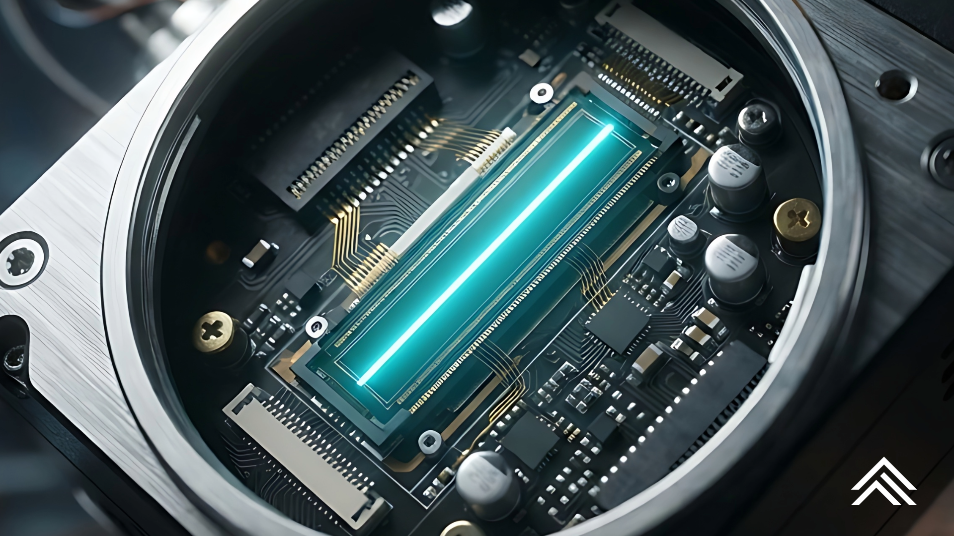
Thermoset composites are a strong option for sensor housings when the design calls for electrical isolation, corrosion resistance, thermal stability, low weight, or RF transparency. Typical candidates include glass-fiber-reinforced epoxy, phenolic, polyester/BMC, vinyl ester, and – where mechanical or thermal demand warrants it – glass/epoxy or quartz/epoxy laminates.
The material system has to be selected around the sensor physics, not just the housing function. A construction that works well for an isolated electronics package may be the wrong choice for an antenna, a magnetic sensor, a pressure diaphragm, a chemical-wetted probe, or a precision temperature sensor.
Where Composites Fit Well
Thermoset-composite sensor housings are a good match for:
- Industrial process sensors in corrosive, wet, salt-spray, UV-exposed, or washdown environments.
- Electrical and power-system sensors, where dielectric strength, tracking resistance, flame performance, and isolation from live parts matter.
- RF, microwave, GNSS, radar, and antenna-adjacent housings, using nonconductive, low-loss constructions such as glass/epoxy or quartz/epoxy — provided dielectric constant and loss tangent are controlled.
- Magnetic-field and current sensors, where a nonmagnetic enclosure avoids the field distortion that ferromagnetic steels can introduce.
- High-voltage instrumentation, partial-discharge monitoring packages, and embedded electronics enclosures.
- Automotive, rail, aerospace, marine, and off-highway sensors, particularly where metal corrosion and mass are penalties.
- Cryogenic or thermally isolated assemblies – though resin toughness, CTE mismatch, permeability, and thermal-cycling durability need qualification.
Thermoset composites are already widely used in electrical enclosures generally, since a single formulation can combine high dielectric strength, arc/track resistance, heat resistance, flame retardance, corrosion resistance, and molded-in attachment features.
Why Use a Thermoset Composite?
| Requirement | Thermoset-composite advantage | Design implication |
|---|---|---|
| Electrical isolation | Glass-reinforced epoxy, phenolic, polyester, and vinyl ester can provide high dielectric strength and tracking resistance | Useful around energized conductors, sensor PCBs, HV terminals, and insulated mounting locations |
| Chemical/corrosion resistance | Proper resin selection resists many aqueous, salt, fuel, solvent, and process-chemical environments | Vinyl ester often deserves consideration for aggressive corrosion service; validate against the actual fluid and temperature |
| Temperature stability | Crosslinked matrices don’t soften and melt the way thermoplastics do | Select resin by continuous-use temperature, glass transition temperature (Tg), and thermal-aging behavior – not just short-term peak temperature |
| Low mass | Composite enclosures can be substantially lighter than aluminum or steel alternatives | Valuable on moving equipment, drones, aerospace structures, field instruments, and elevated installations |
| RF transparency | Nonconductive glass- or quartz-reinforced systems can be made radio-transparent | Avoid carbon fiber or conductive fillers near antennas unless shielding is intentional |
| Nonmagnetic behavior | Glass-fiber systems are intrinsically nonmagnetic | Helpful for Hall, magnetometer, compass, and proximity-sensing environments |
| Dimensional stability | Fiber orientation and laminate architecture can control stiffness and expansion in a preferred direction | Use symmetric/balanced laminate design and control moisture conditioning for precision interfaces |
| Molded features | BMC/SMC and molded thermosets can incorporate bosses, ribs, inserts, seals, cable exits, and connector geometry | Good for part consolidation at production volume |
Composite enclosures have documented benefits in weight reduction, chemical/fluid resistance, durability, and electromagnetic shielding when conductive architectures are used deliberately. Depending on reinforcement and formulation, thermoset composites can also offer high heat resistance, low heat transfer, flame performance, and nonmagnetic/RF-friendly behavior. Discover some of the reasons today’s engineers and designers choose thermosets.
Material-System Choices
Glass-fiber/epoxy
A general-purpose option for rugged instrument housings, electrical isolation, and machined low-to-medium-volume parts. It offers good stiffness, strength, dielectric properties, and dimensional stability, and is available as machined laminate, prepreg/cured shell, compression-molded, filament-wound, or resin-transfer-molded parts. Watch moisture uptake, which can alter dimensions and dielectric performance – edge sealing and resin chemistry both matter here. For tighter precision, use balanced/symmetric constructions and avoid letting fiber orientation drive warpage around flat sealing faces.
Polyester or vinyl-ester BMC/SMC
Often a practical fit for medium-to-high-volume sensor bodies, junction-box-style housings, covers, bases, and terminal enclosures, with a clear path to molded ribs, bosses, screw features, and insert overmolding. Polyester BMC and vinyl ester systems are already used in electrical enclosures for their dielectric and environmental-resistance properties. Prefer vinyl ester when chemical exposure, moisture resistance, or corrosion margin is the driving requirement, and check shrinkage, knit/weld lines, fiber exposure at sealing surfaces, and insert pullout after thermal cycling.
Phenolic composites
A fit where flame, smoke, heat, and arc resistance dominate, alongside low-cost molded electrical performance – phenolic composites are a common choice for legacy electrical housings, terminal structures, and high-heat insulated components. Phenolics are more brittle than many epoxy/vinyl-ester alternatives, so they’re generally better suited to robust geometry than to thin, tightly sealing, cosmetic shells.
Quartz/epoxy or low-dielectric glass/epoxy
Suited to radome-like sensor covers, antenna enclosures, RF windows, and high-frequency packages. Quartz reinforcement can be preferable to common E-glass when dielectric behavior, high-frequency loss, or consistency is critical. RF performance depends on the entire stack – resin, fiber volume fraction, laminate orientation, wall thickness, moisture state, coatings, fasteners, and nearby conductive structures – so characterize the finished molded/cured construction at the relevant operating frequency; generic resin data isn’t sufficient for RF design.
Carbon-fiber thermoset composite
Use only where conductivity is an intentional feature – for structural stiffness, ESD dissipation, or tailored EMI shielding. It’s usually a poor choice around antennas, inductive coils, magnetic sensors, capacitive sensors, and electrically isolated circuits unless carefully engineered, and galvanic corrosion becomes a real risk where carbon composite contacts aluminum or other susceptible metals in a wet environment.
Critical Design Traps
1. EMI shielding versus RF transparency
A conventional glass-reinforced composite is generally electrically insulating and relatively RF-transparent – it does not automatically provide EMI shielding. If the electronics need shielding, consider a conductive coating, metallization, conductive paint, veil, or plated mesh; a localized shield around electronics while retaining an RF window over an antenna; and conductive gaskets with 360° connector termination, since apertures, seams, and cable entries otherwise dominate leakage. Conversely, if the housing encloses an antenna, conductive fibers, metal coatings, carbon-loaded compounds, metal inserts, and even nearby mounting hardware can detune or attenuate it.
2. Sensor thermal coupling
For temperature, heat-flux, infrared, or thermal-conductivity-sensitive sensors, the housing’s low thermal conductivity can help or hurt: it can thermally isolate electronics from a hot external environment, but it can also slow the sensor’s response or create thermal gradients. Where rapid temperature response is required, use a metallic sensing tip, a thin controlled wall, or a dedicated thermal path rather than expecting a composite shell to behave like aluminum or stainless steel.
3. Moisture and dimensional change
Glass-reinforced epoxy laminates can absorb moisture, particularly through cut edges and exposed fibers, affecting sealing-face flatness, precision optical or MEMS alignment, dielectric properties, mass and stiffness, and freeze–thaw or thermal-cycle durability. Design with sealed edges, gasket compression margin, moisture-stable resin selection, and conditioning/qualification at the real temperature-humidity profile.
4. Threaded connections and inserts
Repeatedly loaded threads cut directly into a fiber-reinforced thermoset are often less reliable than metal inserts. Use molded-in brass, stainless, or aluminum inserts where compatible; through-bolts with load-spreading washers for laminate shells; compression-limit sleeves for gasketed clamping interfaces; and isolated inserts or barriers where galvanic couples are possible, especially with carbon composite. Avoid placing inserts too close to thin walls, sharp internal corners, or highly stressed fiber discontinuities.
5. Sealing and machining
A sensor housing only works if it survives its ingress-protection and environmental test plan. Machine critical gasket lands after cure when dimensional control is demanding, avoid exposed chopped-fiber texture at O-ring lands, and use radii and adequate local thickness around mounting ears, cable glands, and fasteners. Specify flatness, surface finish, and compression-stop strategy explicitly, and validate under pressure, thermal cycling, vibration, chemical exposure, and UV as applicable.
A Practical Selection Guide
| Sensor/housing situation | Likely good approach | Main caution |
|---|---|---|
| Outdoor isolated electronics sensor | Glass/polyester BMC or vinyl-ester molding | UV coating, gasket design, condensation venting |
| High-voltage current/voltage sensor | Glass/epoxy, phenolic, or flame-retardant BMC | Creepage/clearance, CTI, tracking, partial-discharge behavior |
| Chemical-process sensor head | Vinyl ester composite shell, possibly with fluoropolymer liner | Full chemical compatibility at concentration and temperature |
| RF/GNSS/radar sensor cover | Quartz/epoxy or controlled glass/epoxy | RF characterization of the final laminate and geometry |
| Magnetometer/Hall sensor | Nonmagnetic glass/epoxy or molded glass-filled thermoset | Keep metallic inserts and fasteners outside the sensitive field region |
| Temperature probe enclosure | Composite electronics body plus metal sensing tip | Response time and thermal gradient |
| EMI-sensitive electronics enclosure | Conductive composite or metallized nonconductive composite | Seams, cable penetrations, grounding, and coating durability |
| Cryogenic package | Toughened glass/epoxy or a carefully selected specialty system | Matrix cracking, CTE mismatch, permeation, and thermal-shock qualification |
Bottom Line
For a typical industrial sensor body, glass-reinforced thermoset composites are often a sound alternative to die-cast aluminum, steel, or conventional thermoplastics – particularly where environmental durability, dielectric isolation, low weight, corrosion resistance, or controlled electromagnetic behavior matter.
The right approach usually isn’t “a composite replacement for metal” in the abstract. It’s a housing designed around the sensing element: nonconductive glass/quartz systems where RF or magnetic transparency matters, conductive layers only where shielding is required, metal inserts and localized thermal paths where those functions matter, and moisture, sealing, thermal-cycling, and chemical exposure qualified on the finished assembly.