

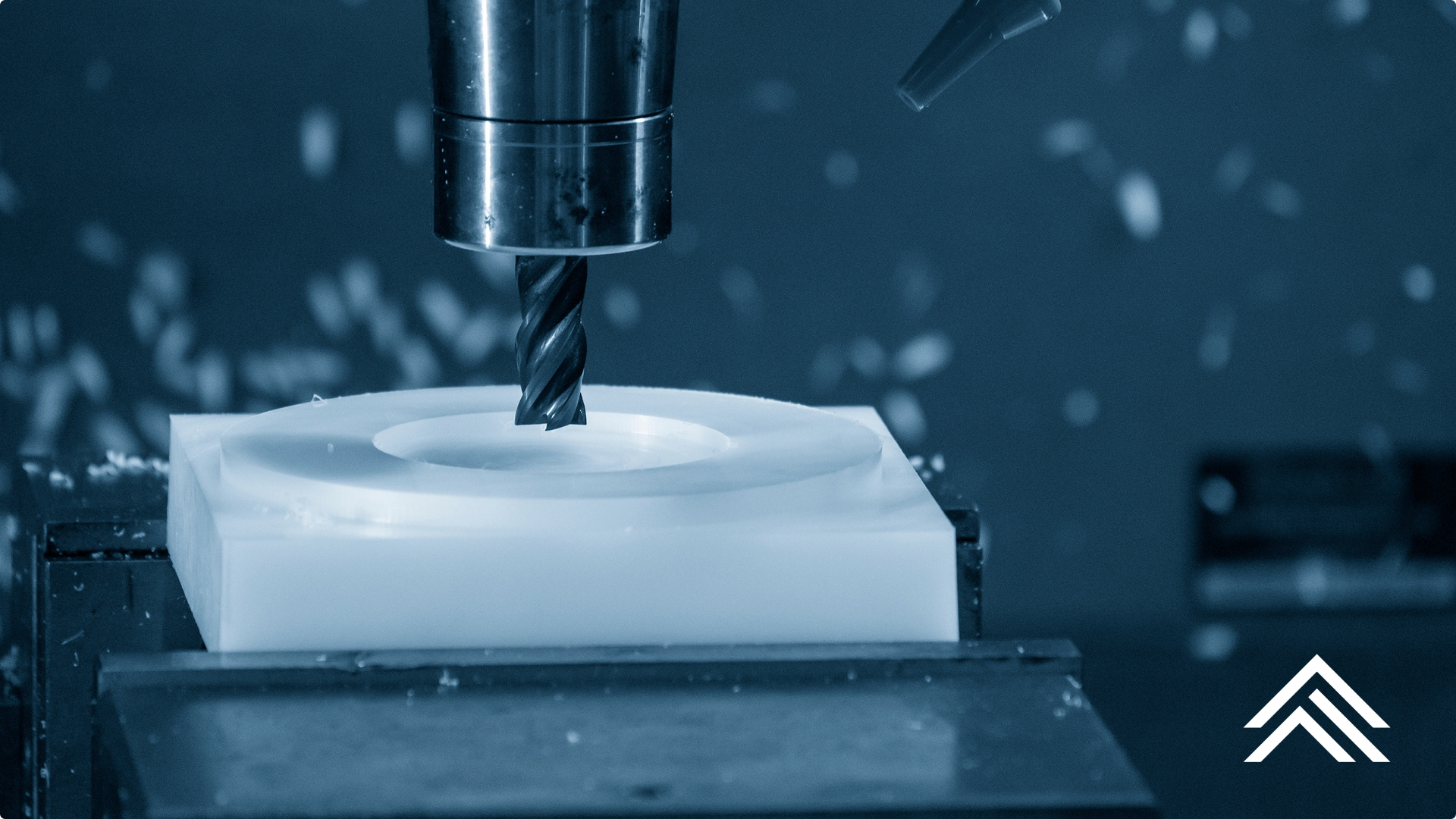
How machining processes, material behavior, and inspection practices determine whether an engineering plastic or composite part works in the assembly.
A batch of machined glass-epoxy insulating plates arrives from a new supplier. Every hole diameter on the inspection report is in tolerance. On the assembly line, the locating pins won’t seat.
The drawing wasn’t wrong, but it wasn’t complete. It toleranced the size of the locating hole and not its position. And where the drill exited the plate, a ring of frayed fibers narrowed the opening. Nobody had said how much of that was acceptable.
Plastic parts move in ways metal parts mostly don’t. They grow with heat, swell with moisture, shift when internal stress is released, and bend under clamping force. Laminates add a grain, much like wood. A part can meet its drawing and still cause trouble in assembly or service.
The quickest way to catch these problems is to understand what causes them. This guide walks through the processes, material behavior, and inspection practices behind them, from material selection through supplier qualification.
The Cuts: Machining Operations and What They Make
Every feature on a drawing implies an operation. Knowing which one helps you read a quote and see where the cost and risk sit.
Milling spins a multi-edge cutter against a part held in place. Face milling makes flat surfaces. End milling cuts pockets and slots. Profile milling follows a contour. Mounting plates, insulating supports, and housings with several machined faces usually start here.
Turning reverses the arrangement: the part spins and a stationary tool cuts it. Straight turning reduces an outside diameter, and facing squares the end. Bushings, rollers, and spacers are turned. Many lathes also carry powered tools that mill or drill features without moving the part to another machine.
Routing also uses spinning cutters, mostly on sheet and plate. CNC routers offer large beds and vacuum hold-down for profiling, trimming, and pocketing big flat parts. Routing and milling overlap. Part size, workholding, and tolerances decide which machine a shop uses.
Sawing and cut-off turn stock into blanks, the starting pieces for later operations. A blank carries a machining allowance: extra material reserved for finishing. That is why raw stock size and finished part size are different numbers, and why an RFQ should keep them separate.
Drilling makes a hole. Boring enlarges and trues an existing one. Reaming removes a thin layer to refine size and finish. A drilled hole is not a precision bore. Call out the diameter, tolerance, and geometry, and let the supplier choose the process.
Countersinking cuts a cone for a flat-head screw. Counterboring cuts a flat-bottomed pocket for a fastener head. Both remove material under the fastener, so check the wall left behind during design review.
Tapping cuts internal threads with a tap. Thread milling cuts them with a rotating tool on a programmed path. Plastic threads have limits. Thread engagement, the number of assembly cycles, and material strength decide whether to machine threads or install a threaded insert, a separate component that carries the threaded connection.
Chamfering cuts an angled edge. Deburring removes leftover material from cutting. An edge break lightly softens a sharp corner. “Break all sharp edges” leaves room for interpretation; a dimensioned chamfer does not. That difference matters near seals, electrical interfaces, and mating parts.
Grinding removes material with abrasives for specific size or finish needs. Broaching drives a toothed tool through the part to form keyways and shaped openings. Both are specialty operations. Confirm they suit the material and geometry before designing around them.
Ask your supplier: Which operations does this part need, and which features drive the number of setups?
The Machine: CNC Capability and Cutting Conditions
A quote is a prediction about a process. Here is how that process is built.
CNC (computer numerical control) means programmed instructions drive the machine. CAD defines the part geometry, and CAM turns it into toolpaths, the routes the cutter follows.
Three-axis machines move along X, Y, and Z. Five-axis machines add two rotary axes so the tool can reach more faces. In indexed machining, the part or tool is repositioned between cuts. In simultaneous five-axis machining, all axes move during the cut. More axes can mean fewer setups, but not every part needs them.
A setup is one way of holding and locating the part for a group of operations. Each new setup means handling the part again and re-establishing its position, which can add variation between features. Workholding and fixturing keep the part secured and supported. Plastics flex under clamping load. A thin wall that measures correctly in the vise can spring out of shape once it is released. 1
Roughing removes most of the excess material. Finishing brings features to final size and surface. Depending on the material and stock condition, a shop may add cooling, stabilization, or stress relief between the two so the part settles before the final cuts.2
Four sets of numbers describe how hard the tool is working:
- Spindle speed (RPM): how fast the tool rotates.
- Cutting speed: how fast the cutting edge travels across the material. It depends on tool diameter as well as RPM.
- Feed rate: how fast the tool advances through the part. In milling, chip load is the feed per tooth.
- Depth of cut and stepover: how deep and how wide the tool engages on each pass.
These settings work as a set. Raising the RPM does not produce a better process on its own. Plastics hold heat at the cut, so tool choice and material-specific parameters matter. Chip evacuation clears cut material so the tool doesn’t recut it and build more heat. 1
Tool geometry covers edge angles, flute shape, and edge preparation. Tool wear is the cutting edge degrading with use. Glass reinforcement is abrasive, so wear builds faster in composites, and a dull edge can leave frayed or broken-out features. A supplier should tie tool replacement to feature quality and measured results.3
Ask your supplier: How many setups will this part take, and how will you support the thin or flexible features?
The Material: Behavior That Shows Up After the Cut
A machined metal part mostly stays the shape it left the machine. A plastic part keeps responding to heat, moisture, internal stress, and load. Here is what drives that behavior.
Thermoplastics such as PEEK, acetal, and nylon soften and melt when heated. Thermosets, including cured epoxy and phenolic laminates, are crosslinked and do not remelt. Too much cutting heat damages both, but by different mechanisms.
Filled and reinforced plastics contain additives that change their properties. Short glass fibers in a thermoplastic and woven glass fabric in a laminate are different structures, and they machine differently. “Nylon” or “glass-epoxy” is not enough for an RFQ. Name the grade and the reinforcement.
Thermal expansion is size change with temperature. The coefficient of thermal expansion (CTE) puts a number on it per degree. Many unfilled plastics expand several times more than steel. If a plastic part fits against metal or operates across a temperature range, the fit on the inspection bench may not be the fit in service. 1
Residual stress is stress locked inside the material. Machining away stock upsets that balance, and the part can distort. Stress relief reduces internal stress. Annealing is a controlled heat treatment for suitable thermoplastics, run on a schedule matched to the grade and geometry. It is not a default step for every plastic part. 2
Moisture absorption changes the dimensions of susceptible materials. Conditioning brings the material to a defined environmental state before machining, inspection, or use. If fit depends on moisture, state the condition the part is measured in. Otherwise two measurements of the same part can disagree. 2
Three kinds of shape change that are easy to confuse:
- Warpage: the overall shape distorts, and the plate is no longer flat.
- Deflection: the part bends under a load, whether from a clamp, a cutter, or a measuring probe.
- Creep: the part slowly changes shape while carrying a sustained load.
Each answers a different question. Does it stay flat? Does it bend during assembly? Does it hold its shape after months under load?
Ask your supplier: What condition will the part be inspected in, and does that match how it will be used?
The Grain: How Laminate Structure Affects Machining
Laminates behave a bit like plywood. They are built in layers, they have a direction, and they can be damaged in ways solid plastics are not.
A laminate is bonded layers of reinforcement and resin. The resin surrounding the reinforcement is the matrix. Glass-epoxy and cotton-phenolic are two common pairings, and each machines differently.
Fiber orientation is the direction the reinforcement runs. Anisotropy means properties change with direction. Where a part is cut from the original sheet can affect how it performs. If orientation matters to function, put it on the drawing or in the material requirements.
There are four ways machining can damage a laminate:
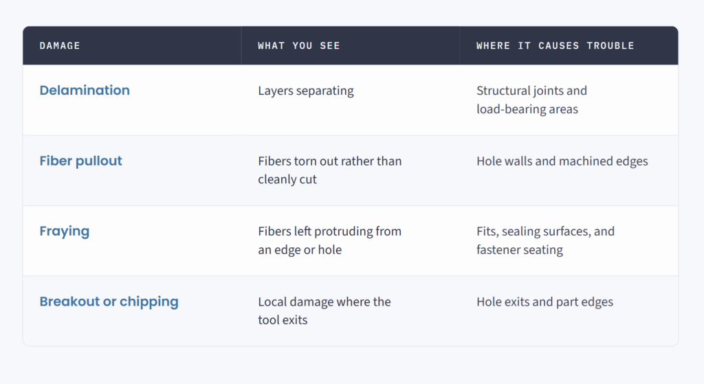
A part can pass every dimensional check and still carry this damage. Where edge or hole-wall quality matters, define what is acceptable on the drawing. 3
Ask your supplier: How do you control breakout at hole exits, and how will you inspect for it?
The Proof: How Drawings and Inspection Define a Good Part
The drawing defines what an acceptable part is. How it is written decides what gets checked, and how.
A dimensional tolerance sets how much a feature’s size or location can vary. GD&T (geometric dimensioning and tolerancing) controls characteristics such as form, orientation, and position. A datum is the reference that features are located and measured from.
Flatness controls the form of a surface. Parallelism controls its orientation relative to a datum. Position controls where a feature sits, under the conditions the drawing states. A tight hole diameter does not guarantee an accurate hole location, as the plate in the opening example shows. You may need both callouts.
Surface finish describes the texture a process leaves behind. Ra is one common roughness parameter: the average deviation of the surface profile from a mean line. A good Ra value says nothing about delamination, cracks, or fiber damage. Call those out separately when they matter.
Accuracy is how close results land to the target. Repeatability is how consistently they land in the same place under the same conditions. Process capability compares a stable process’s variation to the specification limits, and it requires real production data. A good prototype shows the part can be made. It does not show the part can be made the same way across a production run.
Metrology is the science of measurement. A coordinate measuring machine (CMM) evaluates dimensions and geometry from measured points on the part. How the part is supported, how much force the probe applies, and the room temperature all affect the result. A flexible part can measure differently when it is held differently.
Ask your supplier: How will the part be supported during inspection, and at what temperature?
Putting It to Work in NPI and Sourcing
These concepts pay off when they change a design or a quote before production starts.
Design for manufacturability (DFM) reviews how geometry and requirements affect production. Watch for deep pockets, thin walls, small internal corner radii, and tight relationships between opposite faces. Each affects tool reach and workholding. Raise them while a design change is still practical.
Back to the insulating plate from the opening. A DFM review would have caught three gaps. The locating hole needed a position tolerance, not only a diameter. It may have needed a finishing pass rather than drilling alone. And the drawing needed a limit on breakout at the hole exit.
A complete RFQ includes:
- Material grade and any permitted substitutions
- A controlled drawing revision and a matching CAD model, when available
- Critical dimensions, clearly identified
- Edge, hole-wall, and surface requirements
- Expected quantities for prototype and production
- Required documentation
- Service conditions that affect material choice or dimensional acceptance
When comparing suppliers, ask how each proposed process controls the features your assembly depends on. Cover setup strategy, material stability, inspection method, and what changes between prototype and production volumes. The answers show whether a quote reflects the application or only the outline of the part.
Technical References
- Mitsubishi Chemical Group. Machinist’s Toolkit. General machining guidance for engineering thermoplastics.
- Ensinger. Frequently Asked Questions on Machinable Plastics. Guidance on machining, dimensional stability, moisture, and internal stress.
- Atlas Fibre. The Challenges of Machining Composites. Composite machining damage and its implications for component performance.