

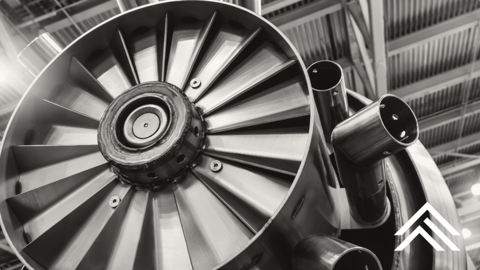
Large-part CNC machining is often the most practical way to produce oversized components from advanced plastics and thermoset composite laminates. Well suited to low- and moderate-volume programs and complex geometries, “large parts” are those that are too large, or too costly, to mold.
Machining a large plastic part is not simply a matter of scaling up the process used for machining smaller components (micromachining). As part size increases, conditions and factors including thermal expansion, internal stress, material deflection, moisture absorption, and even workholding pressure can have a greater effect on the finished geometry.
Successful large-part machining begins with a process designed around the material, the part’s functional requirements, and the conditions in which it will be inspected and used.
Large plastic parts require a different machining strategy
Advanced plastics behave differently from metals under cutting forces, clamping pressure, and temperature changes. Those differences become more pronounced across a large surface or long span.
The primary challenges include:
- Thermal movement: Most plastics expand and contract more than metals. Cutting heat, shop temperature, and inspection temperature can all affect dimensions.
- Residual stress: Extruded, molded, cast, and laminated stock can contain internal stress. Removing material (especially from one side) may allow the blank to twist, bow, or change shape.
- Low stiffness: Many polymers deflect under tool pressure or clamp load and spring back after machining.
- Creep: Sustained fixture pressure can leave an impression or gradually distort a component during a long machining cycle.
- Heat sensitivity: A dull tool or poor chip evacuation can cause rubbing, melting, smearing, discoloration, or an irregular edge.
- Moisture response: Hygroscopic materials such as nylon can gain or lose moisture, changing both dimensions and mechanical properties.
- Long-span variation: A tolerance that is achievable on a small bore or local feature may not be realistic across the entire length of a large plate.
This is why large-part drawings should distinguish between local feature tolerances and overall envelope requirements. A shop may be able to hold a close tolerance on a bore, pocket, or mounting pattern while the acceptable flatness or overall length of the free-state part is necessarily broader.
Material selection affects machinability and dimensional stability
“Plastic” describes a broad group of materials with very different mechanical, thermal, and moisture-related behavior (check out Atlas Fibre’s Material Comparison). Resin family, grade, reinforcement, stock form, and material condition all influence the machining strategy.
| Material family | Common large-part applications | Machining Consideration |
|---|---|---|
| HDPE and UHMW-PE | Liners, wear strips, guides, chemical-processing components | High thermal movement and creep; easily deflected by cutting and clamping forces; can produce stringy chips and burrs |
| Acetal (POM) | Manifolds, bushings, gears, mechanical components | Generally machines cleanly and offers good dimensional stability relative to many unfilled thermoplastics |
| Nylon (PA) | Sheaves, rollers, wear components, structural parts | Tough and wear-resistant, but moisture absorption can materially change dimensions |
| PVC and CPVC | Ducts, tanks, manifolds, corrosion-resistant equipment | Require effective heat and chip control; coolant and cleaning chemistry must be compatible |
| Polycarbonate | Guards, viewing panels, transparent housings | Tough but susceptible to scratching, residual stress, and chemical-induced crazing |
| PET and PBT | Electrical, wear, food-processing, and dimensional components | Often machine cleanly; performance varies by grade and service environment |
| PPS, PSU/PPSU, and PEI | Aerospace, electrical, medical, and fluid-handling components | Provide higher-temperature performance but still require control of heat and residual stress |
| PEEK | Semiconductor, aerospace, medical, and high-performance industrial parts | Excellent thermal and chemical performance; high stock cost makes process control and scrap prevention especially important |
| G-10/FR-4, GPO-3, and phenolic laminates | Electrical insulation, structural supports, cryogenic components, fixtures | Stiff and dimensionally stable; reinforcement is abrasive and requires dust control, suitable tooling, and breakout prevention |
For large format precision machined components, the material specification should identify more than the resin family. It may also need to define:
- Exact grade and approved equivalents
- Stock form, such as cast plate, extruded plate, molded slab, or laminated sheet
- Starting thickness, thickness tolerance, and machining allowance
- Annealed, stress-relieved, or otherwise stabilized condition
- Reinforcement, fillers, color, flame rating, or electrical classification
- Moisture-conditioning requirements
- Material certification and traceability
- Inspection temperature and expected service-temperature range
A material that performs well in one application may be poorly suited to another. UHMW-PE, for example, can be an excellent liner material but a difficult choice for tightly controlled hole spacing over a long span. A glass-epoxy laminate offers greater stiffness and electrical insulation, but its abrasive reinforcement requires a different tooling and dust-management strategy.
A five-part process for controlling large-part distortion
1 ) Begin with stable, conditioned stock
When dimensional stability is critical, use annealed or stress-relieved stock where appropriate and available. Allow the blank to reach a stable shop temperature before precision machining.
A typical rough-rest-finish process may include:
- Condition the blank at a controlled temperature and humidity.
- Rough-machine the part while leaving a uniform finish allowance.
- Release or lightly re-fixture the component.
- Allow it to cool and stabilize.
- Re-establish the datums and finish critical features.
Some materials benefit from a controlled stress-relief cycle between roughing and finishing. Any thermal treatment should follow the material manufacturer’s recommendations; polymers respond differently based on resin chemistry, reinforcement, crystallinity, and prior thermal history.
The essential principle is straightforward: do not finish a large plastic component while it remains in the thermal and mechanical state created by aggressive roughing.
keep reading below
2) Balance material removal
Removing a large volume of material from only one face of a plate can release stress unevenly and cause the part to bow or twist after unclamping.
More stable approaches include:
- Alternating material removal between opposing faces
- Roughing deep pockets in multiple stages
- Leaving consistent finish allowance on walls and floors
- Using balanced toolpaths that avoid concentrating heat in one area
- Opening large holes and windows progressively
- Retaining temporary ribs, tabs, rails, or perimeter stock until late in the process
The objective is to preserve stiffness and release internal stress gradually as the part approaches its final geometry.
3) Support the part without forcing it flat
Large plastic blanks can be distorted by vises, toe clamps, or strap clamps. If the fixture forces a bowed or flexible blank into an artificial position, the machined surfaces may move when the part is released.
Low-distortion workholding options include:
- Broad soft jaws that distribute pressure
- Vacuum fixtures for flat, nonporous components
- Fixture plates with support points beneath thin or highly machined areas
- Controlled low-pressure pneumatic or hydraulic clamps
- Locating pins with light lateral restraint
- Sacrificial tabs or perimeter frames
- Contoured nests for irregular geometries
Sacrificial adhesives where mechanical clamps would damage or deform the part
Thin sections should be supported as close as practical to the cutting zone. Fixture design must also account for tool access, chip evacuation, inspection datums, and how the part will be released and re-established between operations.
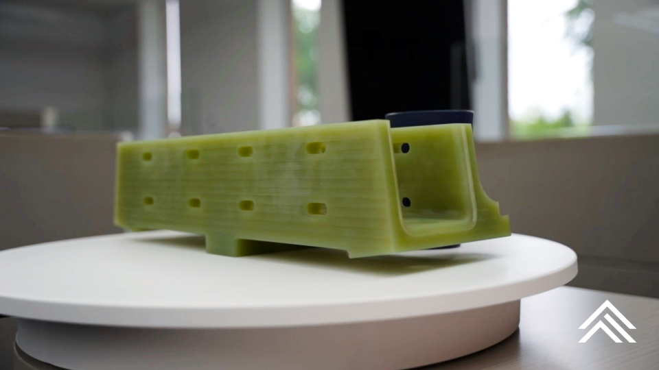
4) Control cutting heat and remove chips
The cutting edge should form and evacuate a chip cleanly. When a tool rubs instead of cuts, heat enters the workpiece and increases the risk of dimensional drift, melting, smearing, or surface damage.
Common process controls include:
- Sharp tools with geometry suited to the material
- Positive rake and polished cutting edges where appropriate
- Single-flute or low-flute-count tools when additional chip space is needed
- Sufficient feed per tooth to avoid rubbing
- Moderate radial engagement and staged axial depth in deep cavities
- Air, vacuum extraction, or a verified compatible coolant to clear chips
- Cooling and stabilization before final passes or inspection
Coolant selection should account for chemical compatibility, contamination limits, bonding or coating operations, and downstream cleaning requirements.
Reinforced composite laminates require another layer of process control. Glass fibers and cured resin systems are abrasive, and the resulting dust must be captured using appropriate extraction, filtration, housekeeping, and personal protective equipment.
5) Finish functional features after stabilization
Critical interfaces should generally be completed after the majority of stock has been removed and the part has reached a more stable condition. Depending on the design, final operations may include:
- Datum surfaces
- Precision bores and bearing fits
- Mounting-hole patterns
- Sealing surfaces
- Insert and threaded features
- Critical flatness zones
- Final perimeter cuts and thin webs
For close-tolerance work, inspect the part in a defined thermal condition and in the same support state specified on the drawing.
How to tolerance large machined plastic parts
The right question is not simply, “Can this shop hold ±0.001 inch?” A more useful question is:
Can this tolerance be maintained on this feature, across this span, in this material, after the part is unclamped, stabilized, shipped, and exposed to its service environment?
Tolerance capability depends on several interacting factors:
- Feature size and distance from the datum
- Material coefficient of thermal expansion
- Expected operating-temperature range
- Moisture absorption or conditioning
- Part thickness and structural stiffness
- Stock form and residual stress
- Fixture orientation and support
- Machine travel, geometry, and thermal condition
- Inspection equipment and measurement method
- Whether the requirement applies in the fixture or in the free state
A practical drawing often uses a hierarchy of requirements:
- Critical fits: Apply close tolerances only to bores, slots, sealing features, and other functional interfaces.
- Mounting patterns: Control position from datums that represent how the part is installed.
- Long dimensions: Use realistic tolerances based on material movement and total span.
- Flatness: Define only where function requires it and state the support condition during inspection.
- Free-state geometry: Specify whether the part must comply after removal from the fixture and after a defined stabilization period.
For example, a large electrical-insulation panel may require close control of a bearing bore and mounting pattern while allowing more variation in an unconstrained outer edge. Applying the same tight tolerance to every dimension can add cost without improving the assembly.
Design guidelines that reduce cost and risk
Design decisions made before quoting can materially improve machining yield, dimensional stability, and cycle time.
- Keep wall thickness reasonably uniform.
- Use ribs, returns, or other structural features instead of requiring extreme flatness from a thin, unsupported panel.
- Add practical internal corner radii.
- Avoid deep, narrow cavities unless tool access, holder clearance, support, and chip removal have been evaluated.
- Provide accessible datum surfaces for each required setup.
- Consider threaded metal inserts where assembly loads or repeated service would damage threads in the base material.
- Maintain adequate hole-to-edge distance, particularly in brittle or reinforced materials.
- Preserve temporary support around thin walls and open profiles until late in machining.
- Identify cosmetic surfaces and acceptable clamp or fixture marks.
- Specify reinforcement or laminate orientation when it affects stiffness, strength, dielectric performance, thermal movement, or edge quality.
Early collaboration between the design engineer and machine shop is especially valuable for oversized parts. Minor changes to a tolerance, corner radius, wall thickness, datum, or blank size can eliminate a setup or prevent an unstable feature.
Special considerations for thermoset composite laminates
G-10/FR-4, GPO-3, phenolic, and other thermoset laminates are generally stiffer and more dimensionally stable than many unfilled thermoplastics. However, they present their own machining challenges:
- Reinforcement accelerates tool wear, which can gradually reduce dimensional accuracy and edge quality.
- Drilling and through-cutting can cause exit-side breakout without proper tool geometry and backing support.
- Excessive thrust, poor support, or a dull cutting edge can contribute to delamination.
- Laminate architecture and orientation can affect stiffness, expansion, strength, and surface appearance.
- Dust extraction and containment are essential process requirements.
- Sheet thickness variation and moisture condition may still matter in electrical, vacuum, and cryogenic applications.
For large insulation panels with extensive cutouts, it is often beneficial to rough the windows and openings before finishing critical mounting and datum features. This allows the panel to release stress before its most important positional relationships are established.
What to include in an RFQ
A complete request for quote helps the manufacturer evaluate material availability, machine capacity, fixturing, inspection, and dimensional risk before production begins.
Include:
- A 3D model and dimensioned drawing
- Finished part envelope and starting blank dimensions
- Material grade, stock form, and approved substitutes
- Required material condition and certifications
- Functional tolerances separated from noncritical dimensions
- Datum scheme and a description of the assembly interface
- Flatness requirements and inspection support condition
- Operating temperature, humidity, chemical, dielectric, vacuum, or cryogenic conditions
- Quantity, repeat-order expectations, and target schedule
- Cosmetic requirements and acceptable machining marks
- Inspection documentation, such as a first article or dimensional report
- Permission for staged machining, multiple setups, or a fabricated alternative when appropriate
Plan the material, machining, and inspection together
Large part CNC machining succeeds when the component is treated as a thermally active, stress-sensitive structure – not as an oversized metal plate. Stable stock, balanced material removal, low-distortion workholding, effective heat and chip control, and properly sequenced finishing operations all contribute to a repeatable result.
The best solution may be a monolithic thermoplastic component, a machined thermoset laminate, or a fabricated or modular assembly. Evaluating those options early helps balance dimensional stability, mechanical performance, electrical requirements, environmental exposure, lead time, and cost.
Atlas Fibre supports large part CNC machining of advanced engineering plastics and thermoset composite laminates, from material selection and stock supply through precision fabrication and inspection. Share your drawing, material specification, and operating requirements with our team to begin a manufacturability review.