

Drill a hole a few millimeters wide in a block of FR-4, and you’re doing ordinary machining. Drill a hole half a millimeter wide – about the width of a strand of thick hair – in the same material, and you’re suddenly fighting a different set of physics.
That’s the strange thing about micromachining phenolics, G-10, FR-4, and glass epoxies: shrinking the tool doesn’t just shrink the job. At that scale, a laminate stops behaving like a uniform plastic and starts acting like what it actually is – a composite, built from layers of resin and reinforcement that don’t cut the same way twice.
A sliver of edge breakout. A few microns of tool wobble. A part that shifts almost imperceptibly in its fixture. None of that would matter on a full-sized bracket. On a microfeature, any one of them can eat the entire tolerance band. Getting it right means controlling everything at once – material, tooling, spindle accuracy, workholding, heat, dust, and inspection – because the margin for error has essentially vanished.
The key takeaways:
- The reinforcement fibers, not just the resin, decide how the material cuts.
- Tools need to be sharp, low-runout, and wear-resistant; there’s no room for a dull edge.
- The part needs full support and a clean entry/exit, or it delaminates.
- A tool is “done” when precision starts slipping, not when it finally snaps.
Why This Stuff Fights Back
Phenolics, G-10, FR-4, and G-11 are thermoset laminates, which means their resin is cured solid – it won’t soften and curl off in a chip the way a thermoplastic does. Instead, cutting these materials fractures the resin and shears or snaps the reinforcement fibers, throwing off dust and fine particulate rather than clean shavings.
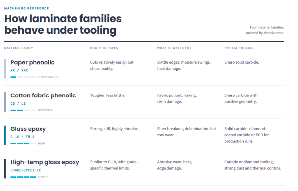


G-10 and FR-4 both use woven glass cloth in an epoxy matrix – FR-4 just adds a flame-retardant requirement on top. As a cutter moves across that weave, it’s constantly crossing glass bundles, resin pockets, and crossover points where the two meet. The cutting load never stays constant, and that shows up as inconsistent edge quality, hole geometry, and tool wear along a single pass.
There’s No Official Line Where “Small” Becomes “Micro”
Nobody hands you a caliper reading and says “this is officially micromachining now.” The real question is simpler: has the feature gotten small enough that ordinary process variation – the stuff you’d never notice on a bigger part – is now the dominant factor?
Runout. A wobble in the spindle that’s trivial on a large end mill can be a huge percentage of a micro tool’s diameter. Suddenly one cutting edge is doing most of the work, wearing unevenly, and leaving oversized, rough features. The toolholder, collet, spindle, shank, and how far the tool sticks out all feed into this.
Edge condition. A sharp tool shears cleanly through resin and reinforcement. A dull one rubs, builds heat, spikes cutting force, and drags fibers loose from the matrix instead of cutting them. In abrasive glass-epoxy grades, the part can start degrading before the wear is even visible on the tool.
Chip load. It’s tempting to slow the feed rate every time a tool breaks, but that can backfire. Drop feed-per-tooth below the tool’s own edge radius, and instead of cutting, it starts rubbing and plowing, generating more heat, wearing faster, and damaging the matrix further.
Part support. Thin laminate can flex or chatter between clamping points. At full size that’s a nuisance; at microfeature scale, that same flex becomes a dimensional error or breakout on the exit side. The fixture has to support the material right up to the cutting zone without squeezing or distorting it.
Picking Tools That Can Actually Survive the Job
For paper and cotton phenolics, short, sharp solid-carbide tools are a solid starting point. Positive rake geometry cuts cutting force, and a reduced-helix design can help keep thin stock from lifting off the fixture mid-cut.
Glass-reinforced grades are a tougher fight – they’re simply more abrasive. Solid carbide handles prototypes, short runs, and plenty of precision work. Diamond-coated carbide or polycrystalline diamond earns its cost when production volume is high enough, when abrasive wear is causing measurable drift in feature size, or when the shop needs predictable tool-change intervals instead of surprises.
Whatever tool you’re running, keep unsupported length as short as possible. Composite-specific flute geometries can help manage axial force and dust evacuation, but at the smallest diameters, fixture support and toolpath strategy often matter more than what’s printed on the tool’s spec sheet.
Milling Small Slots and Pockets Without Wrecking Them
Stable micromilling comes down to controlling how much of the tool is in contact with material at any moment:
- Don’t slot full-width if you don’t have to. Limit radial engagement wherever the geometry allows.
- Rough, then finish separately. Leave a thin, even allowance so the finishing pass has a consistent load to work with.
- Take shallow axial steps, especially near thin walls and unsupported edges.
- Keep the toolpath smooth. Arcs and gradual lead-ins avoid sudden load spikes.
- Never let the tool sit still mid-cut – dwelling in place builds heat and wear fast.
- Test your cutting direction. Climb milling is often the better starting point, but the laminate’s construction and surface-ply orientation can change that.
It also helps to save exterior profiles for last, so the surrounding stock keeps supporting internal features until the very end. Tabs, a perimeter frame, or a sacrificial carrier can hold the part together until final separation.
Drilling a Hole You Can Barely See
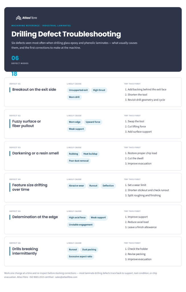
Microdrilling might be the single hardest operation here, because the drill has to stay perfectly aligned while somehow clearing abrasive dust out of a bore that’s barely bigger than the drill itself.
- Back up the exit face with flat sacrificial material.
- Keep drill runout and unsupported length to a minimum.
- Peck only enough to clear debris and manage heat – too much re-entry adds wear and alignment risk.
- Retract far enough to actually clear the dust, rather than repacking it into the flutes.
- Track diameter, taper, position, and edge quality on both entry and exit as you go.
- For anything critical, consider whether a secondary sizing pass makes sense.
High aspect-ratio holes raise the stakes further – wander, taper, dust packing, and breakage all become more likely. Don’t borrow a cycle from metal cutting and hope it works; prove it on representative laminate first.
The Fixture Is Usually the Real Problem
A surprising number of “cutting” problems are actually workholding problems. A good fixture supports as much of the underside as possible, restrains the part close to where the cutting happens, prevents movement without preloading the laminate, and still leaves room for dust extraction or coolant.
Vacuum fixturing works well on flat stock with good local support. For small blanks, mechanical clamps, low-residue adhesives, sacrificial plates, or custom nests are often the better call – just validate any adhesive and its removal process so it doesn’t split thin webs or leave contamination behind.
Material conditioning matters too. Paper and cotton phenolics are more sensitive to moisture than glass-epoxy laminates, so tight-tolerance stock should sit and stabilize in a controlled environment before it’s machined or inspected.
Dust Isn’t a Side Issue – It’s Part of the Process
These materials don’t produce chips in the traditional sense; they produce fine particulate. That makes dust control a performance issue and a safety issue at the same time.
Source capture should sit as close to the cut as possible. An air blast can help clear the tool, but only if it works with the extraction system instead of scattering dust across the shop. Guarding, filtration, housekeeping, and PPE should all follow the material safety data sheet and your facility’s exposure-control program.
Dry machining works fine for a lot of applications, as long as extraction keeps the cutting zone clear without letting heat build up. Wet or mist-assisted machining can help control temperature and airborne particulate on tougher glass-epoxy jobs, but it brings its own list of chores: removing abrasive slurry, drying parts before inspection, watching out for moisture-sensitive phenolic grades, and making sure everything stays compatible with downstream bonding, coating, or cleanliness requirements.
Turning This Into a Repeatable Process
Speed-and-feed charts are a reasonable starting point, but they can’t account for every laminate construction, every supplier, every tool geometry, or the condition of a specific machine. Real qualification means testing on material that actually represents the production part:
- Verify spindle, holder, and tool runout.
- Minimize tool stickout.
- Build rigid, full-area support wherever practical.
- Start with a fresh tool suited to the reinforcement you’re cutting.
- Compare a rough-and-finish strategy against the simplest stable alternative.
- Inspect feature size, location, taper, chip condition, delamination, and finish.
- Measure results after a defined run of features or parts.
- Set the tool’s retirement point where quality starts slipping – not where the tool finally breaks.
Take drilling a 0.5 mm through-hole in 1.5 mm FR-4 as an example. Picking a small enough drill is the easy part. The real job is combining low runout, minimal projection, rigid exit support, real dust evacuation, a proven cycle, and a defined replacement interval – all at once. Just slowing the feed until the drill stops snapping doesn’t solve the problem; it usually just trades fracture for rubbing, heat, and a slow decline in hole quality.
Designing the Part So It’s Actually Machinable
- Keep microfeatures away from unsupported exterior edges when you can.
- Avoid razor-thin webs between holes, slots, and profiles.
- Use realistic internal radii instead of sharp blind corners.
- Flag which surfaces are cosmetic, sealing-critical, or electrically critical.
- Spell out what level of chipping, fiber exposure, or breakout is actually acceptable.
- Use inserts or through-fasteners for threads that will be assembled repeatedly or carry real load.
- Call out the exact laminate grade, thickness, construction, and flame requirement; “fiberglass” or “phenolic” alone isn’t enough information to machine to.
- Note any post-machining cleaning, drying, sealing, or inspection steps up front.
The Bottom Line
Micromachining phenolics and glass epoxies is entirely doable – it just requires treating the material as the composite system it is, not a smaller version of the plastic you’re used to cutting. Tool sharpness, runout, fixture support, cutting engagement, dust control, and inspection all carry more weight as features shrink.
Keep the tools sharp and wear-resistant, keep runout to a minimum, support the part close to the cut, shear the material instead of rubbing it, manage dust at the source, and judge tool life by the quality of the feature – not by how long the tool lasts before it snaps.
Atlas Fibre works with thermoset composite laminates and precision CNC machining daily, across parts ranging from small, intricate features to production runs – and can help work through material selection, geometry, and tolerancing early in a design.