

(And How to Fix It)
Delamination, fiber breakout, chipped edges, and premature tool wear are common challenges when drilling G-10, FR-4, and phenolic laminates. Here’s what causes them and how to improve hole quality.
Drilling a hole through a piece of metal is relatively straightforward. The cutting edges engage the material, chips form, and the drill advances through the workpiece.
Try the same operation on a sheet of G-10, FR-4, or phenolic laminate, and things get more complicated.
The hole might look perfectly clean from above, only to reveal fractured fibers and separated layers on the opposite side. A drill that produced excellent results at the beginning of a production run may start leaving rough edges as its cutting surfaces wear. Or a hole that meets its diameter tolerance may still contain microscopic damage that compromises the finished component.
The challenge isn’t necessarily the equipment. It’s the material.
Thermoset composite laminates don’t behave like metals or conventional plastics. Their layered construction, reinforcing fibers, and cured resin systems create unique machining challenges, particularly when drilling.
Understanding how those materials respond to cutting forces is the first step toward preventing defects and producing consistent, high-quality holes.
Why Thermoset Laminates Are Difficult to Drill
Most industrial thermoset laminates consist of reinforcement materials impregnated with resin, consolidated under heat and pressure, and cured into rigid sheets, rods, or tubes.
The reinforcement may be woven glass fabric, cotton fabric, or paper. The resin is typically epoxy or phenolic, depending on the grade. Those differences matter.
- Glass-epoxy laminates, including G-10, FR-4, and G-11, combine high mechanical strength and electrical insulation properties with abrasive glass reinforcement. Their fibers can accelerate cutting-tool wear and contribute to edge chipping and delamination when drilling conditions aren’t controlled.
- Cotton phenolic laminates, including NEMA Grades C, CE, L, and LE, use woven cotton reinforcement. Canvas grades typically have a coarser weave, while linen grades use finer fabric. These differences can influence the quality of small drilled features, edge definition, and the amount of fiber fuzzing produced during machining.
- Paper phenolic laminates, including XX and XXX grades, have a different reinforcement structure and may exhibit chipping, breakout, or localized cracking depending on the material, geometry, and cutting conditions.
Despite their differences, these materials share an important characteristic: they’re layered composites held together by a cured thermoset resin.
Unlike thermoplastics, which soften when heated, cured thermosets do not remelt into a workable state. Excessive drilling heat can damage or degrade the resin rather than produce conventional melting.
The combination of reinforcement, rigid resin, and laminate interfaces is what makes drilling so demanding.
Problem #1: Hole Looks Clean on Top, but Exit Is Splintered
The defect: Exit delamination and push-out
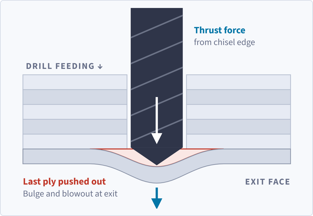
One of the most common and recognizable drilling defects in composite laminates is exit delamination.
The problem occurs as the drill approaches the bottom surface of the material.
Throughout the operation, the drill generates axial thrust as it cuts. When the tool approaches breakthrough, the remaining material beneath the drill becomes progressively thinner.
Eventually, that remaining laminate may no longer have sufficient strength to resist the thrust.
Instead of being cut cleanly, the bottom layers bend, separate, or fracture.
The result is a damaged exit surface that may include chipped edges, protruding fibers, or separation between laminate layers.
This defect can be particularly problematic for electrical insulators, precision spacers, and structural components where the edge condition around drilled holes affects fit or performance.
How to fix it
Start by examining the support beneath the workpiece.
A sacrificial backing plate, firmly positioned against the exit surface, can help support the remaining laminate as the drill breaks through. This reduces the opportunity for unsupported layers to flex and separate.
Next, inspect the cutting tool. Worn edges can increase thrust and make exit damage more likely.
Drill geometry also plays a role. Certain composite-specific drill geometries are designed to reduce thrust or improve cutting action through reinforced materials.
Finally, review breakthrough feed. A controlled reduction in thrust near the exit may improve results, but excessively low feed can introduce rubbing and heat.
The objective is to maintain an effective cutting action without imposing unnecessary force on the final laminate layers.
Problem #2: Top Layers Begin to Peel Away
The defect: Entry delamination
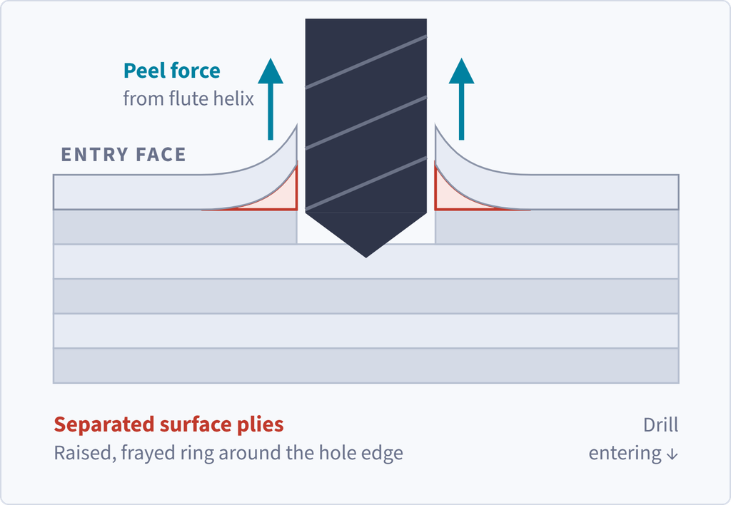
Exit delamination isn’t the only way laminate layers can separate.
Entry delamination, sometimes called peel-up, occurs at the upper surface as the drill first enters the material.
In this case, the cutting action can lift or peel the upper reinforcement layers away from the material beneath them.
The mechanism differs from exit push-out, which is caused by thrust acting on an increasingly unsupported layer.
Entry delamination is more closely associated with the interaction between drill geometry, cutting action, and the upper plies.
How to fix it
Begin with drill condition and geometry.
Dull or damaged cutting edges can increase undesirable cutting forces. Depending on the laminate and drilling setup, certain flute and point geometries may contribute to lifting forces near the entry surface.
Verify that the workpiece is securely clamped and that the tool enters the material without excessive vibration or instability.
For demanding applications, evaluate drill designs intended specifically for glass-reinforced or laminated composite materials.
An important distinction: entry and exit delamination are different failure mechanisms. A change that improves one may not necessarily eliminate the other.
Problem #3: Hole Is the Right Diameter, but the Walls Are Rough
The defect: Fiber fraying, fuzzing, and pull-out
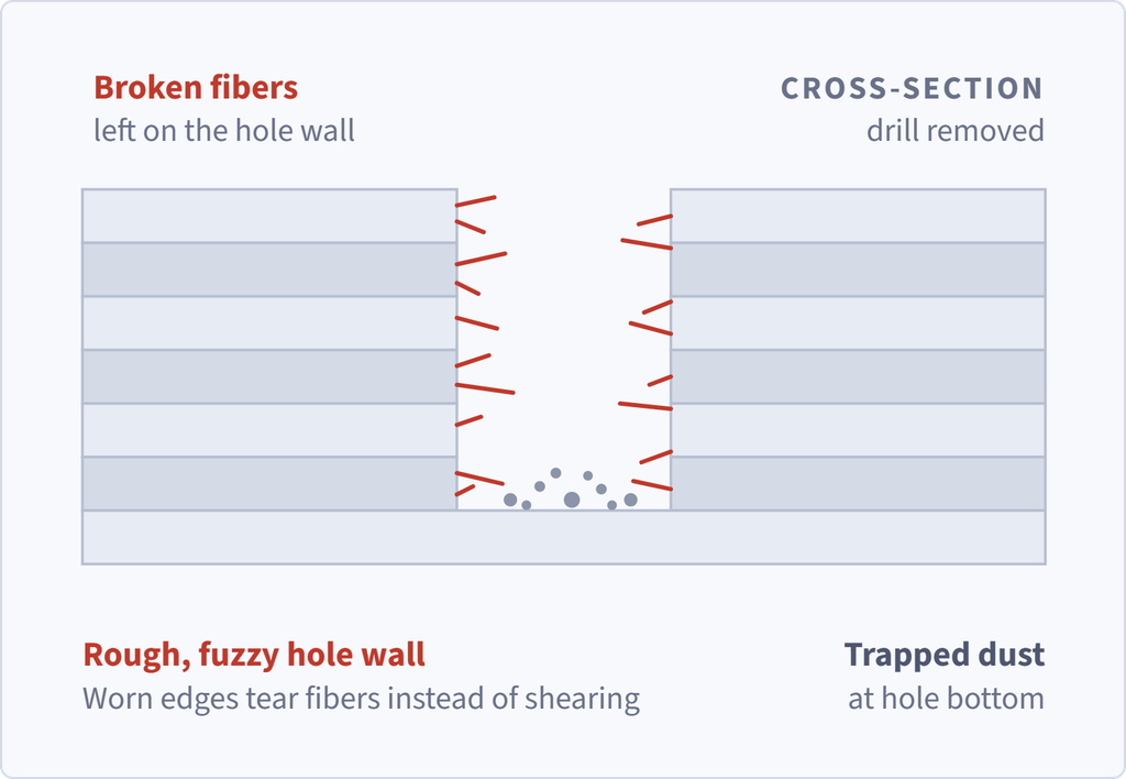
A drilled hole can meet its dimensional requirements and still have poor edge or surface quality.
In glass-reinforced laminates, the drill may fracture fibers instead of cutting them cleanly. Exposed or broken fibers can remain along the hole wall, creating a rough or uneven finish.
In cotton phenolic laminates, the problem can appear as fuzzing or torn fabric fibers, especially when the reinforcement has a relatively coarse weave.
Tool wear is a major consideration.
Glass fibers are highly abrasive, and repeated drilling gradually changes the condition of the cutting edges. As the tool becomes less effective, the cutting action may shift toward crushing and tearing rather than cleanly shearing the reinforcement.
That can produce inconsistent hole quality as a production run progresses.
How to fix it
Inspect the cutting edges for wear, chipping, or damage.
Solid carbide tooling is a common starting point for drilling reinforced laminates. For demanding production requirements, diamond-coated carbide or polycrystalline diamond (PCD) tooling may provide improved wear resistance and cutting-edge consistency.
However, tool selection should account for the laminate grade, hole diameter, depth, production volume, and required quality.
Chip and dust evacuation also matter.
Unlike many metals, glass-reinforced thermosets produce fine particulate debris during drilling. If that debris remains trapped in the hole, it can interfere with the cutting action and contribute to additional surface damage.
Effective extraction and evacuation help maintain more consistent drilling conditions.
The key is to preserve a sharp, controlled cutting action rather than allowing the tool to tear through reinforcement.
Problem #4: The Hole Edge Chips or Fractures
The defect: Edge chipping and breakout
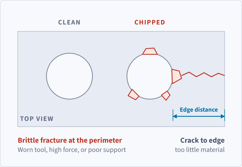
Not every damaged hole is caused by delamination.
In some cases, small pieces of material fracture away from the hole perimeter without obvious separation between laminate layers.
This can occur at the entry surface, exit surface, or along the hole wall.
Thermoset laminates contain relatively rigid resin systems, and their response to concentrated cutting forces can include brittle fracture.
Chipping may become more pronounced when the tool is worn, the cutting forces are excessive, or the workpiece isn’t adequately supported.
The material grade and reinforcement type also influence the result.
How to fix it
First, determine whether the damage is isolated to the hole perimeter or associated with deeper laminate separation.
Then inspect tool condition, workholding rigidity, and the cutting parameters.
Vibration and unstable fixturing can increase localized loading and contribute to inconsistent edge quality.
For holes located near part edges or closely spaced features, review the surrounding geometry as well.
Sometimes the issue isn’t simply the drilling process. The available material between the hole and the nearest edge may be insufficient to withstand the drilling forces without damage.
When chipping persists, the part design, hole location, and material orientation may require further review.
Problem #5: The Resin Looks Burned or Discolored
The defect: Thermal damage and resin degradation
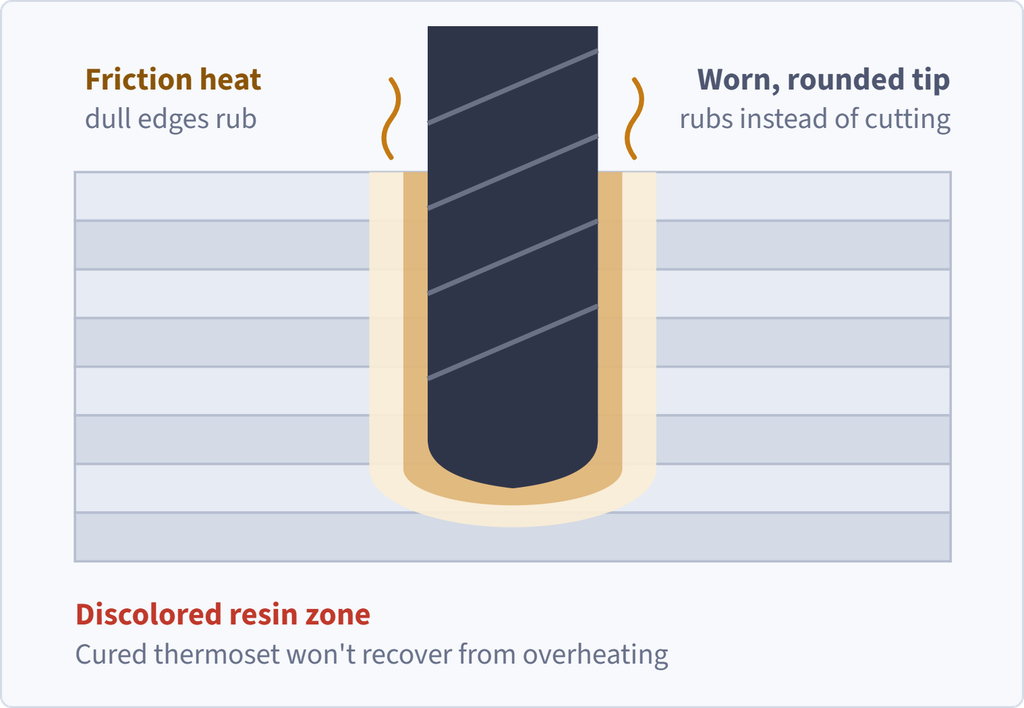
Thermoset composites can tolerate demanding operating environments, but drilling can generate localized temperatures high enough to damage the resin system.
Excessive heat may develop when cutting edges become dull, the drill rubs instead of cutting, or debris accumulates in the hole.
In some cases, the result is visible discoloration. More severe conditions can produce localized resin degradation or other damage.
Unlike a thermoplastic, a cured thermoset doesn’t simply soften and flow when heated beyond its normal processing range.
That distinction is important because increasing heat can cause irreversible material damage.
How to fix it
Start by inspecting the cutting tool.
Dull edges increase friction, and trapped abrasive debris can aggravate the problem.
Next, review spindle speed and feed per revolution.
Excessive surface speed may generate unnecessary heat, but reducing feed too far can cause rubbing rather than effective cutting.
The objective is to establish a combination that removes material efficiently without excessive friction or thrust.
Finally, evaluate chip and dust removal, particularly for deeper holes.
Appropriate evacuation can help reduce debris accumulation and improve cutting consistency.
Discoloration alone does not establish the extent of damage, so suspect components may require additional evaluation.
Problem #6: Hole Wanders or Comes Out of Round
The defect: Positional error, taper, and dimensional variation
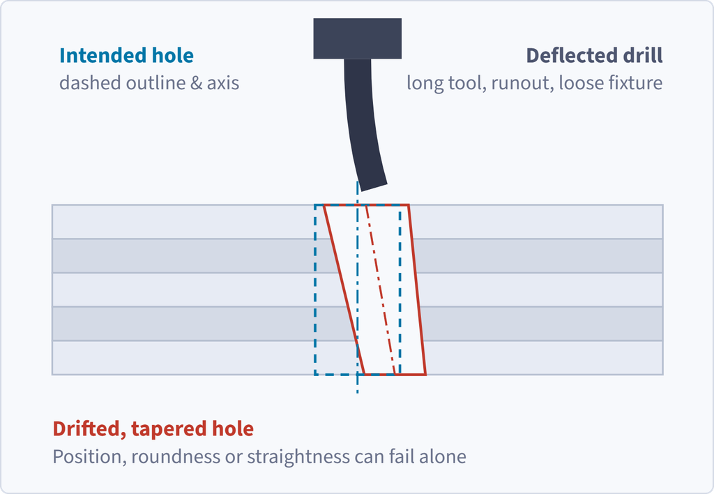
Some drilling defects aren’t immediately obvious.
A hole may have clean edges and acceptable surface quality but still be oversized, tapered, out of round, or positioned incorrectly.
Drill deflection, tool runout, uneven cutting forces, and workholding instability can all contribute.
These problems may become more significant when drilling small-diameter or deep holes, particularly with long, slender tools.
Material variation can also influence cutting behavior.
In reinforced laminates, the drill encounters a combination of fibers and resin rather than a perfectly homogeneous material. That interaction can affect tool loading and the finished geometry.
How to fix it
Begin by verifying the setup.
Check drill runout, holder condition, tool length, and fixture rigidity.
Use the shortest practical drill configuration to improve stiffness.
Review whether the drilling strategy provides adequate guidance and whether a secondary finishing operation is needed to meet demanding tolerances.
For precision holes, distinguish between diameter accuracy, hole position, roundness, and straightness.
A hole can satisfy one requirement while failing another.
The Overlooked Factor: Which Direction Are You Drilling?
One of the most important considerations in laminate machining is the orientation of the hole relative to the reinforcement.
Consider two scenarios.
In the first, the drill passes through the broad face of a sheet, cutting across the stacked layers.
In the second, the drill enters the edge of the sheet, traveling parallel to the laminate layers.
These operations may produce very different results.
When drilling perpendicular to the layers, entry and exit delamination are often important concerns.
When drilling parallel to the layers, the forces generated by the drill may encourage splitting along the laminate interfaces, especially when the hole is close to a free edge or the surrounding material is thin.
This is why material orientation should be considered during component design, not just during machining.
Engineers should clearly communicate critical laminate orientation requirements on drawings and manufacturing documentation.
A hole that appears straightforward in a CAD model may introduce significant manufacturing challenges depending on how the part is oriented within the original sheet stock.
Five Steps to Troubleshooting Composite Drilling Defects
When a defect appears, changing spindle speed or feed rate immediately isn’t always the best solution.
A more reliable approach is to identify the likely failure mechanism and isolate the contributing factors.
1. Identify the defect and its location.
Is the damage at the entry, exit, or along the hole wall? Is the problem delamination, fiber breakout, chipping, thermal damage, or dimensional accuracy?
2. Inspect the drill.
Look for worn or chipped cutting edges, incorrect geometry, excessive tool projection, or runout.
3. Evaluate workholding and support.
Confirm that the part is adequately supported, particularly near the hole exit. Inspect the fixture for movement or vibration.
4. Review the cutting conditions.
Examine feed per revolution, spindle speed, drilling cycle, breakthrough strategy, and debris evacuation. Adjust one parameter at a time and document the result.
5. Inspect and validate the correction.
Measure the finished hole, evaluate edge and wall quality, and confirm that the process produces repeatable results.
For critical components, visual inspection may not be sufficient to identify subsurface damage. Additional inspection may be required depending on the application and acceptance requirements.
The objective is not simply to produce one acceptable hole, but to establish a repeatable process that maintains quality across production.
Better Hole Quality Begins with Part Design
Drilling performance isn’t determined by tooling and cutting parameters alone.
Several design decisions can make a significant difference in the quality and manufacturability of drilled features.
Hole diameter and depth influence tool selection and chip evacuation. Edge distance affects the amount of surrounding material available to resist cutting forces. Laminate orientation changes the way reinforcement interacts with the drill.
Tolerance requirements and functional expectations matter, too.
A clearance hole in an electrical insulating panel may have different acceptance requirements than a precision locating hole or a feature used to secure a structural component.
Similarly, the allowable amount of edge chipping or fiber exposure may depend on the part’s electrical, mechanical, or assembly requirements.
For demanding applications, material selection, hole geometry, tooling, and inspection expectations should be considered together.
The Bottom Line: A Clean Hole Is More Than a Diameter
Drilling thermoset composite laminates requires more than selecting the right drill size and entering a feed rate.
G-10, FR-4, G-11, and phenolic grades combine rigid resin systems with reinforcing materials that respond differently to cutting forces, heat, and tool wear.
When drilling defects occur, the visible symptoms often reveal something about the underlying cause.
Exit delamination may point to excessive thrust or insufficient backing. Fiber breakout may indicate worn tooling or ineffective cutting action. Chipping can suggest excessive localized loading, while thermal damage may reveal friction or evacuation problems.
Understanding those relationships makes it easier to identify corrective actions and establish consistent drilling processes.
Because the real measure of a successful drilling operation isn’t simply whether the hole meets its specified diameter. It’s whether the finished hole meets the part’s dimensional, structural, and functional requirements, consistently.
Precision Composite Machining at Atlas Fibre
Atlas Fibre combines extensive thermoset laminate inventory with in-house CNC machining, precision inspection, and manufacturing expertise.
From G-10 and FR-4 to canvas, linen, and paper phenolics, our team works with customers to evaluate material selection, part geometry, machining requirements, and production considerations.
Explore Atlas Fibre’s Composite Machining Capabilities to learn more about manufacturing precision components from engineered thermoset materials.