

What to Control, and How to Specify it on Drawings for Maximum Part Performance
Two parts can have identical dimensions, come from the same material grade, and still place different material directions along the same load path.
The difference may begin with how each part was positioned within the original sheet.
For thermoset composite laminates, fiber orientation can affect performance, machining decisions, and material utilization. Yet drawings often specify the material and finished geometry without explaining how they must relate.
The goal is to identify the orientation requirements that matter, communicate them clearly, and preserve that information through the entire manufacturing process. That can be a lot to process, so start at the beginning.
What Does “Orientation” Mean Anyway?
There are several different meanings of orientation in the context of machining. Before adding a note to your parts drawing, make sure that you understand these three related concepts.
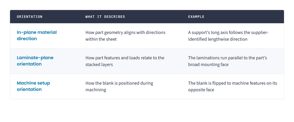
Of course, these relationships are not interchangeable. Rotating a blank on a machine table does not necessarily change the material direction within the finished part. In much the same way, allowing rotation within the sheet does not mean you can (or should) cut the part on its edge from thicker stock.
Keeping these important distinctions clear helps teams (engineering, procurement, manufacturing) communicate the same requirements throughout the production process.
Why Material Direction Affects Performance
Thermoset laminates combine reinforcement with a cured resin system. G10, for example, uses woven fiberglass and glass epoxy resin. Cotton/linen phenolics, on the other hand, use a different reinforcement and resin combination. In the end, their properties depend on how these materials were constructed.
Strength and stiffness can vary be direction
An individual manufacturers’ property tables usually distinguish lengthwise and cross wise mechanical properties. Those differences mean that rotating a part 90 degrees within a sheet can change the properties available along a critical feature.
Consider a long support load in bending. If its design relies on properties measured in one material direction, the finished support must preserve that relationship.
However, “always align the longest dimension with the warp direction” is usually too broad. The appropriate orientation depends on the load case, laminate construction and applicable material data.
Use the supplier’s definitions. Confirm how lengthwise and crosswise directions correspond to warp and fill when those terms apply. Do not assume that an unmarked sheet’s longest edge identifies its material direction.
The laminate plane is a separate consideration
A part cut flat from sheet and an otherwise similar part cut on edge have different relationships between their features and the laminations.
That distinction deserves review wherever a design transfers loads through the laminate thickness or places holes and fasteners near its edges. An in-plane direction arrow alone does not explain this relationship.
When layer orientation matters, show it explicitly in a section view.
How Orientation Affects Manufacturing Decisions
Orientation requirements influence more than the finished part’s load path. They also shape how the manufacturer selects stock, produces blanks, and plans machining.
Edge drilling requires particular attention
A hole drilled through a sheet’s broad face crosses the laminate layers. A hole drilled into its edge may run parallel to them.
These configurations require different consideration. Norplex-Micarta’s fabrication guide specifically warns of splitting when drilling parallel to laminations in paper and cotton fabric grades. It recommends restraint and more frequent chip clearing for that condition.
Edge-oriented holes should therefore be identified during the manufacturing review. Their placement may affect support, drilling strategy, and the feasibility of nearby thin features.
Material direction and cutting direction are different controls
The required orientation of the finished part does not fully determine how a cutter should approach each feature.
Tool geometry, cutting engagement, support, and machining direction also affect results. For glass-based laminates, Atlas Fibre recommends climb milling to reduce the tendency toward delamination.
The drawing should communicate the required material-to-part relationship. The manufacturing plan should establish how to machine it successfully.
Orientation alone does not guarantee dimensional stability
Avoid treating a direction requirement as a universal solution for bowing, twisting, or dimensional movement.
Isola’s processing guidance illustrates why qualification matters: its DE104 laminate can move differently in warp and fill during printed wiring board processing. The guide calls for characterizing movement under the actual process conditions. Those results should not be converted into universal movement predictions for machined G-10 or FR-4 parts.
For close-tolerance components, establish the relevant material and process behavior before prescribing an orientation as the solution.
The Cost Tradeoff: Direction Requirements Limit Nesting Options
Nesting software arranges parts within sheet stock to improve utilization. An orientation requirement reduces the available arrangements.
If a part must follow one material axis, an end-for-end reversal may be acceptable while a quarter-turn is prohibited. This can reduce the number of parts available from a sheet.
The cost effect depends on part geometry, sheet dimensions, quantities, and usable remnants. Some layouts change very little; others require substantially more stock.
Necessary orientation controls should remain. Unnecessary restrictions should be removed through engineering review.
For sourcing teams, this also helps explain quote differences. Two suppliers may price the same geometry differently if they interpret an ambiguous orientation note differently.
How to Communicate Orientation on a Drawing
Use a labeled direction arrow tied to defined part geometry, supported by an explicit note. Add a section view when the laminate plane also needs control.
This combination communicates both what must align and what the indicated direction means.
Identify the material direction precisely
Use terminology that matches the applicable material documentation, such as:
- Supplier-identified lengthwise direction.
- Warp direction, where applicable and confirmed.
- Supplier-defined machine direction.
Avoid “grain direction” by itself when it leaves the material axis open to interpretation.
Tie the direction to a specific feature
“Parallel to part length” may work for a simple rectangle, but becomes ambiguous on irregular components.
A clearer reference could be the centerline through two identified holes or a dimensioned axis shown in the drawing.
The requirement should remain understandable if the view is rotated or the drawing is reformatted.
Define the laminate plane separately
If the layers must remain parallel to a mounting face, identify that face and show the relationship in section.
A warp arrow in a top view does not, by itself, establish the required through-thickness orientation.
State which rotations are permitted
Distinguish between:
- A 180-degree reversal within the sheet.
- A 90-degree rotation within the sheet.
- Turning the blank over.
- Producing the part on edge from thicker stock.
Permission for one does not automatically permit the others. If a particular original stock face must become a finished face, specify that relationship separately.
Apply an angular tolerance when needed
Select alignment tolerances from the functional requirement.
Adding an arbitrary ±2-degree or ±5-degree tolerance can create manufacturing and verification work without a demonstrated benefit. A controlled requirement should also have an agreed method of verification.
Example Drawing Notes
The following examples are suggested wording, not prescribed drafting-standard language. Replace bracketed text with released engineering requirements.
For a part requiring a specific in-plane direction:
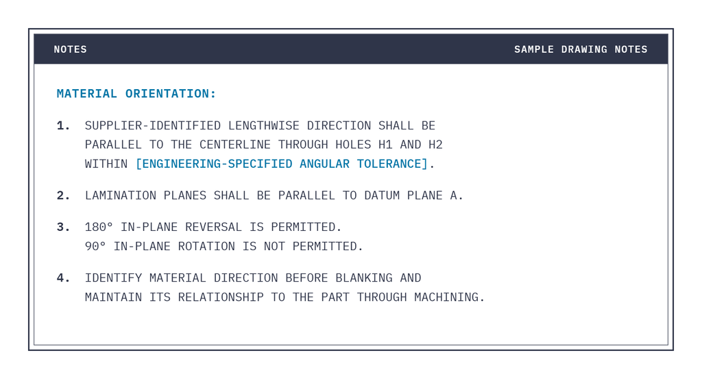
Use actual feature identifiers from the drawing. Place a labeled, double-headed direction arrow along the referenced axis when end-for-end reversal is acceptable.
If only the laminate plane matters, a less restrictive requirement may be appropriate:
LAMINATION PLANES SHALL BE PARALLEL TO DATUM PLANE A.
IN-PLANE MATERIAL ORIENTATION IS UNRESTRICTED.
This preserves the required layer relationship while allowing manufacturing to evaluate additional nesting arrangements.
Preserve the Requirement Beyond the Drawing
An orientation note only works if the information survives production.
Once a sheet becomes separate blanks, its original direction may no longer be apparent. Where orientation is controlled, the production plan should establish how direction identification transfers to blanks and usable remnants.
Agree on the necessary records before cutting. Finished dimensions alone may not demonstrate that the required material orientation was maintained.
Bring Orientation into the Manufacturing Review
Orientation belongs in the conversation before quoting and blanking begin.
At Atlas Fibre, our thermoset manufacturing and precision machining capabilities support reviewing material selection and part geometry together. Share the drawing, critical load paths, and orientation requirements early so those relationships can inform stock selection and machining decisions.
A clear drawing gives manufacturing two essential pieces of information: the material relationships the design requires and the freedom available to produce the part efficiently.
However, indicating “always align the longest dimension with the warp direction” is far too broad. The appropriate orientation depends on hte load case, laminate construction, and applicable material data.
Ultimately, it’s best to use the supplier’s definition. Confirm how “lengthwise” and “crosswise” directions correspond to concepts like “warp” and “fill” when those terms apply. No matter what, don’t assume that an unmarked sheet’s longest edge identifies its material direction.
The laminate plan is a totally separate consideration
A part that is cut flat from a sheet and an otherwise similar part cut on edge have different relatioships between their features and the laminations.
That distinction deserves review whereever a design transfers loads through the laminat ethickness or places holes and fasteeers near its edges. An in-plane direction arrow alone won’t explain this relationship.
When layer orientation matters, show it explicity in a section view.