

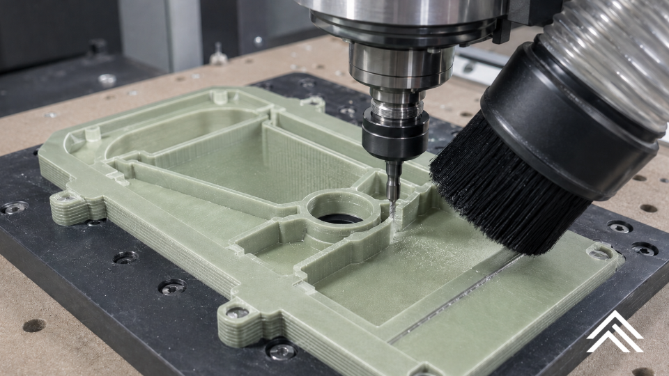
A thin-wall composite part can measure perfectly while it’s still clamped to the fixture – and then cup, twist, or start vibrating the moment it’s released or the wall gets thin enough to flex. That gap between how a part looks on the table and what it does afterward is the central challenge of thin-wall thermoset composite machining.
Machining a thin wall, rib, flange, or perimeter from a thermoset composite laminate is fundamentally a stiffness-and-stress-control problem. Reducing the depth of cut may help, but lighter cuts alone will not prevent a finished part from moving after it leaves the fixture or stop a flexible section from vibrating under the cutter.
For materials such as G10/FR4, G11, glass-phenolic, and paper, canvas, or linen phenolic, a stable process must control three different failure modes:
- Elastic deflection: The component bends under clamping or cutting forces but appears correct while restrained.
- Release warp: Residual stress becomes unbalanced during machining, causing the component to cup or twist after unclamping.
- Chatter and vibration: A wall or web loses stiffness as material is removed, allowing vibration to damage the edge, fracture the resin, or delaminate the laminate (separate its reinforcement layers from one another).
Avoiding these problems requires coordinated decisions about fixturing, tool condition, cutter engagement, operation sequence, and inspection.
Why Thin-Wall Composite Components Move
Thermoset laminates behave differently from metals. Their properties depend on the resin system, reinforcement, weave, and ply direction. Cutting forces and edge quality can change as the tool moves relative to the reinforcement. Glass-reinforced grades are also highly abrasive, so a tool that begins the operation sharp can generate much higher forces as its cutting edge wears.
Several conditions commonly create trouble.
Fixture-induced distortion
A thin workpiece can be forced flat with point clamps or excessive vacuum. While the part is restrained, its dimensions may appear correct. Once the restraint is removed, the stored elastic energy is released and the component springs, cups, or twists.
The fixture should hold the workpiece securely without using force to correct its natural shape.
Unbalanced material removal
Deep pocketing, thinning a wall from one side, or skimming only one face changes the stress balance through the laminate thickness. The component may move during machining, immediately after release, or after it has rested.
When substantial material must be removed from both sides, alternating between faces and leaving similar finishing allowances helps preserve balance around the laminate mid-plane.
Loss of local stiffness
A wall that begins as part of a rigid blank becomes more flexible with every pass. Once its stiffness falls below what the cutting forces and toolpath demand, the cutter may excite the natural vibration modes of the part-and-fixture system.
This is why a finishing pass that looks conservative on paper can still chatter: it may occur after the supporting stock has already been removed.
Material-specific edge failure
Different laminate families fail in different ways. Dull tools in glass-epoxy grades can produce fraying, microcracking, and delamination. Phenolic grades may exhibit brittle chipping, fuzzing, localized cracking, or heat damage to the resin. A successful process must be qualified for the actual grade and laminate construction, not just the nominal material family.
Build Support Into the Fixture
The most reliable fixtures provide continuous, distributed support beneath the thin section. A machined sacrificial subplate, spoilboard, or close-fitting nest can support the nominal flat surface and eliminate air gaps beneath the cutting zone.
Vacuum fixturing can work well when the available surface area provides adequate holding force. Use zoned vacuum, gasketing, and a close-fitting pocket where appropriate. The objective is to retain the component, not pull a distorted sheet flat across unsupported gaps.
For profiles and through-cuts, consider a sandwich arrangement with a sacrificial backup below the laminate and, where the geometry permits, a top retainer or pressure plate. Supporting the exit face helps prevent breakout, splintering, and delamination.
Additional fixturing practices include:
- Avoid point clamps on finished thin walls and webs.
- Place required mechanical clamps over robust stock that will be removed later.
- Use wide, compliant pads and only enough clamping force to resist cutting loads.
- Retain a perimeter frame, tabs, or temporary cross-webs until the final operation.
- Register two-sided components from robust datum features or sacrificial holes rather than a flexible finished edge.
- Ensure the area directly beneath the cutter is supported throughout the toolpath.
The final point is especially important. A fixture may hold the overall blank securely while still leaving a local web unsupported. That local gap can become the source of chatter.
Reduce Cutting Force Without Creating Rubbing
Thin-wall machining (particularly G10 machining) depends on low, predictable cutting forces. That begins with a short-reach, low-runout tool (one that spins true, without wobble at the cutting edge) and a sharp cutting edge.
Solid carbide may be suitable for shorter runs. In glass-filled laminates, diamond-coated carbide or polycrystalline diamond tooling generally provides longer life because the glass reinforcement is highly abrasive. As the edge wears, cutting and thrust forces rise, exactly what a flexible section cannot tolerate. (For more on matching tooling to laminate type and managing wear over a production run, see our post on repeatable machining of abrasive composites.)
Use sharp, composite-specific geometry with a positive shearing action. Compression-style cutters can help control fibers on both faces during through-routing. For holes, composite drill geometries such as brad-point, step, or core drills can reduce exit damage compared with a generic twist drill. Orbital drilling – where the tool follows a small circular path while also feeding downward, rather than plunging straight in – may also be justified for demanding applications.
Keep tool stickout, holder runout, and unsupported wall height as low as practical. When possible, engage the cutting length closer to the shank rather than machining at the end of a long tool.
Maintain a viable chip load
Chip load is the amount of material each cutting edge removes per revolution – in effect, the “bite” the tool takes with each pass. Do not reduce the feed until the cutting edge begins to rub instead of cutting. Rubbing generates heat, erodes the resin, accelerates tool wear, and can make vibration worse.
To lower cutting force, reduce radial engagement (how far the tool reaches sideways into the material) and axial depth (how deep it cuts per pass) first. Then adjust spindle speed and feed together so the cutter continues to form a viable chip. Avoid full-width slotting in material that has already been thinned. Adaptive or trochoidal-style clearing – toolpaths that sweep in curved, partial-width passes instead of cutting a full-width channel – and multiple light radial engagements can reduce lateral force. (Our post on machining thermoset composites for tool life covers chip load targets and process parameters by laminate type in more depth.)
Qualify the cutting direction
Climb milling (where the cutter rotates in the same direction the material is feeding, versus conventional milling, where it rotates against the feed) often produces a clean edge in glass-epoxy and phenolic laminates, but no cutting direction is universally superior. The result depends on the reinforcement orientation, cutter geometry, and support condition.
Run a coupon trial – a small test cut on a sample piece of the actual production laminate – using the production laminate construction. Compare both toolpath directions and inspect the top and bottom faces. The qualified method should be based on the actual edge condition, not a rule borrowed from metal machining.
Use an Operation Sequence That Preserves Stiffness
Operation order can be as important as the selected tool. The goal is to complete force-intensive features while the blank is rigid and keep temporary support around fragile geometry until late in the process.
A practical starting sequence for a thin, flat component is:
- Condition and inspect the stock. Allow the sheet to equilibrate to the shop environment and begin with flat material where possible.
- Machine datums and internal features first. Complete these operations while the stock has maximum support and stiffness.
- Rough both faces symmetrically. Rough Side A, flip the workpiece, and rough Side B while leaving comparable allowances.
- Leave thin walls and the outer contour heavy. Preserve a perimeter frame, tabs, or temporary webs.
- Finish with light, low-force passes. For critical flatness, use matched finishing passes on both faces around the laminate mid-plane.
- Support every through-feature. Drill before fragile profiling when possible and place a backup directly behind the exit surface.
- Finish the outer contour last. Retain tabs or a frame, then remove the remaining connections with a supported, low-force operation.
- Release, dwell, and inspect. Measure the component immediately after unclamping and again after it has relaxed.
If parts repeatedly cup toward the last-machined face, investigate unbalanced material removal and excessive restraint before changing feeds and speeds.
What to Change When Chatter Starts
Before changing parameters, determine whether the vibration originates in the tool and spindle, the fixture, or the workpiece. On thin laminates, the part-and-fixture system is often the source. Simply slowing the spindle may move the vibration without solving it.
Work through the following checks:
- Verify cutting-edge wear, runout, holder condition, and tool stickout.
- Add support directly beneath the cutting zone and eliminate gaps under the wall or web.
- Reduce radial engagement and avoid full-width slots, abrupt reversals, and long unsupported finishing sweeps.
- Change spindle speed by a meaningful amount—often 10% to 20% is more informative than a small adjustment—and recalculate feed to preserve chip load.
- Shorten the unsupported length by changing the sequence or retaining temporary stock.
- Evaluate tool diameter and reach together. A smaller cutter may reduce force, but a larger, shorter tool may provide greater stiffness.
- Break long toolpaths into shorter passes with effective dust evacuation and brief cooling intervals.
This order addresses the structural source of chatter before relying on parameter changes alone.
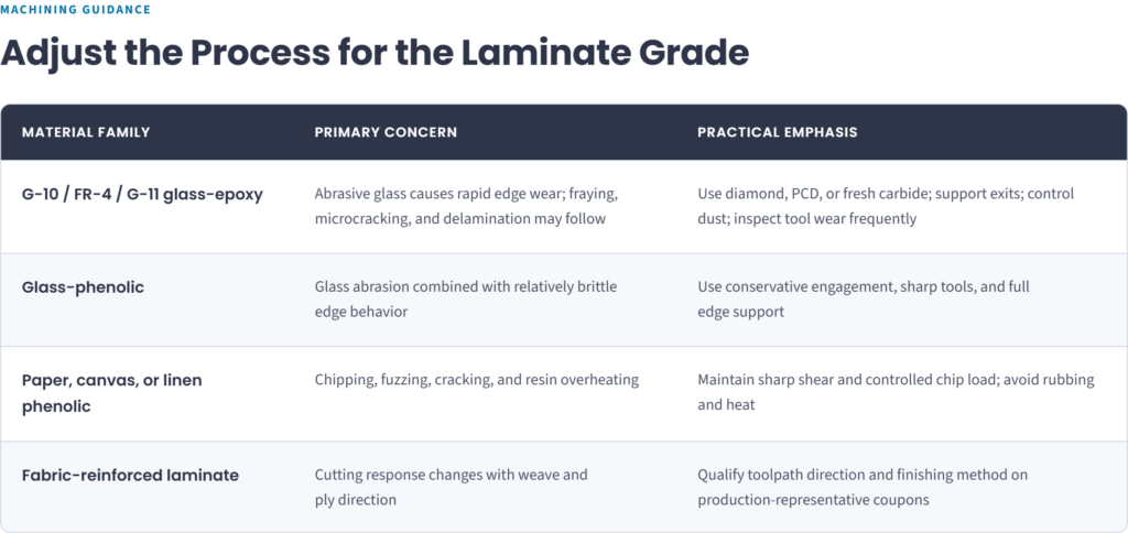
Formal grade designation matters. NEMA LI 1 – the industry specification covering standard grades of industrial laminate – includes multiple epoxy-glass and phenolic paper, canvas, and linen grades. Differences in resin and reinforcement mean that one universal feeds-and-speeds recipe is unlikely to be reliable.
Control Dust, Heat, and Inspection Conditions
Thermoset composites are commonly machined dry with controlled air and effective dust extraction unless the material supplier approves another method. Flood coolant can create an abrasive slurry, and moisture-sensitive laminates may experience delayed dimensional movement. Composite dust requires suitable enclosed collection, personal protective equipment, and disciplined housekeeping.
For repeat production, qualify the process with a focused design of experiments. Useful variables include tool condition, spindle speed, chip load, radial engagement, stepdown, support method, and toolpath direction.
Measure more than dimensions while the part remains clamped. Track:
- Wall thickness
- Flatness immediately after release and after a defined dwell period
- Edge condition, chip-out, and delamination
- Spindle load or vibration signatures
- Tool condition at defined production intervals
These measurements reveal whether the process is stable—or whether the fixture is temporarily hiding movement.
Control Stiffness and Stress From the First Cut to Final Inspection
Successful thin-wall composite machining is not based on a single parameter. It comes from maintaining support, balancing material removal, preserving temporary stiffness, using sharp low-force tooling, and inspecting the component after it has been released from the fixture.
When these controls are planned together, thin G10/FR4, glass-phenolic, and other thermoset laminate components can be machined with clean edges, stable walls, and repeatable flatness.
For additional guidance, explore how to maintain flatness and edge integrity when machining composite sheets or connect with the Atlas Fibre technical project team to discuss the material, geometry, and production requirements for your application.