

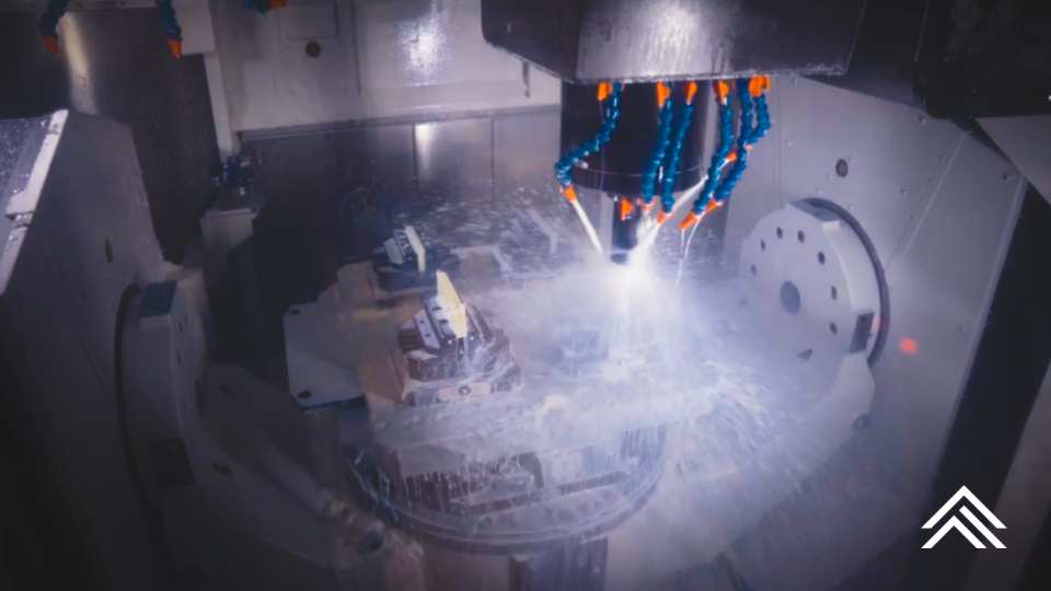
Thermoset composite laminates and thermoplastics are often grouped together as nonmetallic materials. Although they appear on the same prints, arrive in similar stock shapes, and run on the same CNC equipment, machining thermosets requires a distinctly different approach than machining thermoplastics.
That means they do not machine the same way; specifying or sourcing a part as if they do is when edge quality, tolerances, and lead times can go wrong.
The fundamental difference in machining these advanced materials is how each material responds to heat and cutting force. Thermoplastics such as Nylon, Acetal (Delrin), PEEK, and Ultem PEI can soften, deform, or melt as friction raises their temperature. Thermoset composite laminates such as G10/FR-4 and G11, and paper or fabric phenolics, do not melt. Their cured, cross-linked resin matrix and reinforcement are cut instead through a combination of shearing and controlled fracture.
A second difference matters just as much on a drawing: dimensional stability. A cured thermoset holds its size and shape. Many thermoplastics move (expanding with heat, absorbing moisture, or relaxing internal stress once material is removed) which changes how the part must be fixtured, machined, and inspected.
Together, those two distinctions affect nearly every part of the thermoplastic and thermoset machining process: tooling, cutting parameters, workholding, cooling, chip evacuation, and dust collection.
Material Structure Drives the Process When Machining Thermosets
Thermoset composite laminates such as G10, FR-4, G11, and paper or fabric phenolics contain layers of reinforcement bonded within a permanently cross-linked resin system. Depending on the grade, that reinforcement may be woven glass fabric, canvas, linen, or paper.
Once cured, the resin cannot be remelted or reshaped by heat. Machining removes material by cutting through the reinforcement and fracturing the cured matrix, producing chips, fibers, and fine abrasive dust rather than the continuous or curled chips common to thermoplastics.
Thermoplastics such as Nylon, Acetal, PEEK, and Ultem PEI have a different molecular structure. Heat lets the polymer chains move more freely, so the material softens. During machining, uncontrolled friction can cause dimensional movement, melting, smeared surfaces, welded chips, or clogged tool flutes.
The practical difference is straightforward:
- Thermoset machining is largely about controlling abrasiveness, fiber breakout, and delamination.
- Thermoplastic machining is largely about controlling heat, chip formation, and material movement.
Machining Thermosets Like a Pro
Machining thermosets is closer to cutting an abrasive composite than machining an ordinary plastic. The goal is to cut the reinforcement cleanly without lifting, peeling, or separating the laminated layers.
Tooling for Thermoset Machining
Glass-reinforced grades such as G10 and FR-4 are highly abrasive. Solid carbide is commonly used for shorter runs, while polycrystalline diamond (PCD) tooling can provide substantially longer life in repeat production.
Tool geometry should account for the direction of the laminate and the risk of edge breakout. Depending on the feature, suitable tooling may include:
- Diamond-pattern router tools
- Compression cutters
- Down-cut tools
- Brad-point or dagger-style drills
- PCD end mills, routers, and drills
A conventional spiral (up-cut) end mill can pull upward on the top layers of a laminate. Compression or down-cut geometry directs cutting pressure into the material and produces a cleaner edge.
Tool condition is critical. Once an edge begins to dull, cutting forces climb quickly, driving heat, poor finishes, dimensional variation, and delamination.
Feeds and Speeds
Thermosets generally benefit from moderate cutting speeds and enough feed per tooth to keep the tool cutting. Too light a chip load lets the edge rub across abrasive fibers, accelerating wear without improving the finish.
Ideal parameters depend on the grade, thickness, reinforcement orientation, tool diameter, operation, and machine rigidity. The objective is not simply to run slowly. It is to balance tool life against a chip load that produces a clean, controlled cut.
Dust Collection for Machining Thermosets
Machining thermosets (glass-, carbon-, paper-, or fabric-reinforced laminates) can generate fine airborne particulate. Effective source capture should sit close to the cutting tool to protect employees, preserve machine components, and keep the work area clean. Dust collection is part of the machining process, not an optional housekeeping step.
Dry machining thermosets with properly designed extraction is generally preferred. Conventional flood coolant can combine dust and fluid into an abrasive slurry that is difficult to contain and hard on machine components, so any wet process should be engineered specifically for composite machining.
Keep reading below…
Machining Thermoplastics
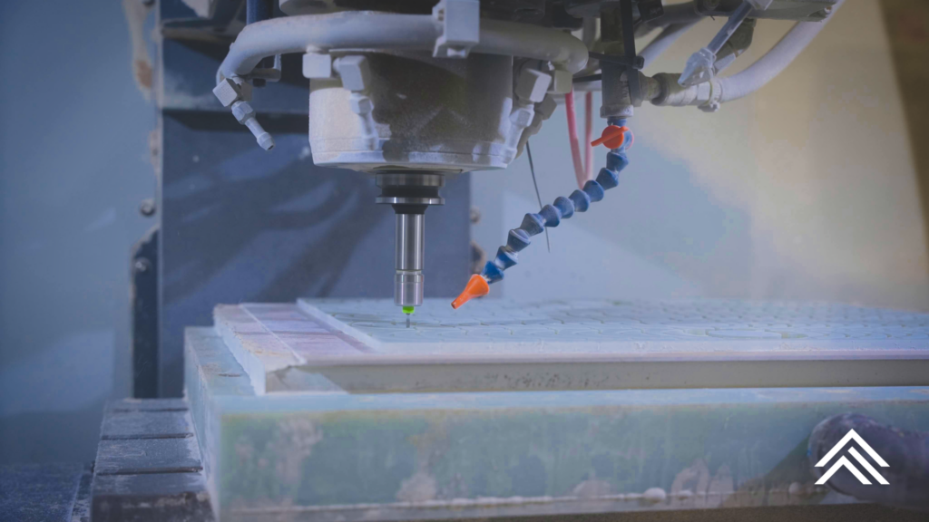
Machining thermoplastics is primarily a chip-forming process. The goal is to create a clean chip and clear it before frictional heat can soften the workpiece or weld material back onto the cutter.
Tooling
Thermoplastics generally require extremely sharp cutting edges, positive rake angles, and generous flute space. Single- and double-flute tools are often effective because they leave room for rapid chip evacuation.
Polished flutes are especially useful in softer or more heat-sensitive materials such as Nylon; they reduce friction and make it harder for chips to adhere to the tool.
Dull tooling does more than spoil a finish. It raises heat and cutting pressure and can cause dimensional instability, deformation, or stress-related cracking.
Feeds and Speeds
Successful thermoplastic machining depends on balancing spindle speed against a productive chip load. Turn the tool too fast while advancing too slowly and it rubs instead of cutting, heat builds locally, and the material softens or smears.
An adequate feed lets the chip carry heat away from the workpiece. The right balance varies substantially by polymer: Nylon, Acetal, PEEK, and PEI should not all run on one generic “plastic” program.
Cooling, Chip Evacuation, and Inspection
Compressed air, cold-air guns, mist systems, or compatible water-soluble coolants can all be used to control temperature and clear chips. The best choice depends on the material, operation, dimensional requirements, and end-use restrictions. Some applications prohibit certain coolants for contamination, chemical-compatibility, or cleanliness reasons, so cooling strategy should be selected alongside the material and manufacturing plan.
Workholding also requires care. Thermoplastics are far less stiff than metals and can deform under excessive clamping pressure, a part may measure correctly while restrained and move once released.
Inspection deserves the same attention. Because many thermoplastics shift with temperature and humidity, parts should be measured under controlled, consistent conditions. A part that passes at the machine can read out of tolerance in QC a few hours later.
Material-Specific Machining Considerations
G10, FR-4, and G11 Glass Epoxy
G10, FR-4, and the higher-temperature G11 are woven-glass epoxy grades. Beyond the abrasive wear and delamination already covered, two things tend to decide part quality in production: hole quality and exit breakout.
Drilling is where glass epoxy punishes a tired edge. Brad-point or dagger drills, paired with a backing board that supports the exit ply, keep holes clean and prevent the last layer from blowing out. FR-4’s flame-retardant chemistry machines much like G10 but can load a tool slightly differently, so holes and edges should be validated on the actual grade rather than assumed from G10 results.
This is also where PCD earns its cost. On repeat production, the tooling premium is usually repaid through consistent edge quality and far fewer tool changes than carbide can deliver in the same run.
Grade XX Paper Phenolic
Paper phenolic is generally less abrasive and easier to machine than glass epoxy, but its layered construction can chip at edges and tool-exit locations.
Sharp carbide tools with positive cutting geometry typically produce good results. Supporting the workpiece with a backing board reduces breakout when drilling through the material or machining across an unsupported edge.
Heat still has to be managed. Excessive tool dwell or a dull cutting edge can scorch the paper reinforcement and leave a darkened edge.
Nylon 6/6
Nylon is tough, flexible, and prone to stringy chips. It also absorbs moisture, which can shift dimensions and should be accounted for when setting tolerances and inspection conditions.
Sharp single- or double-flute tools with polished surfaces support clean chip evacuation. Productive feeds create thicker chips that carry heat out of the cut rather than letting it accumulate in the workpiece.
Rigid, well-distributed workholding matters, but clamping pressure must stay controlled to avoid bowing or distorting the part.
Ultem 1000 PEI
Ultem 1000 offers greater temperature resistance and stiffness than many general-purpose thermoplastics, but sharp tooling and controlled cutting pressure remain essential.
Heavy material removal can release internal stress from the stock shape and cause dimensional movement. Parts with tight tolerances may need a staged process: rough machining, stabilization or stress relief where appropriate, and finish machining after the material reaches equilibrium.
Annealing requirements should be established before production, because the correct cycle depends on the material supplier, stock shape, part geometry, and how much material is being removed.
General Starting Parameters
The ranges below are for preliminary process planning only; starting points, not universal specifications, and published values vary between material and tooling manufacturers. Final parameters should be confirmed through controlled trials using the actual material, tool geometry, workholding, and machine configuration.
| Parameter | G10 / FR-4 | Grade XX Phenolic | Nylon 6/6 | Ultem 1000 PEI |
|---|---|---|---|---|
| Typical tooling | Carbide; PCD preferred for production | Carbide or HSS | Sharp, uncoated carbide or HSS | Sharp, uncoated carbide |
| Surface speed | 200–400 SFM | 400–800 SFM | 800–1,500 SFM | 500–1,000 SFM |
| Metric surface speed | Approx. 60–120 m/min | Approx. 120–240 m/min | Approx. 240–450 m/min | Approx. 150–300 m/min |
| Starting chip load for a 1/4-inch end mill | 0.001–0.003 IPT | 0.002–0.005 IPT | 0.003–0.008 IPT | 0.002–0.005 IPT |
| Typical evacuation or cooling | Dry extraction | Dry extraction | Air or compatible coolant | Air or compatible coolant |
| Primary machining concern | Abrasive wear and delamination | Edge chipping and scorching | Heat, chip wrapping, and deflection | Heat, stress, and dimensional movement |
Machine capability, tool projection, feature geometry, reinforcement, stock condition, and required finish should all be considered before establishing a production program.
Frequently Asked Questions
Can you CNC machine G10 and FR-4?
Yes, and not only can we machine it – we can machine it at scale. G10 and FR-4 can machine well on standard CNC equipment, but the woven-glass reinforcement is abrasive and prone to delamination, so we need sharp carbide or PCD tooling, controlled speeds with an adequate feed, and dust extraction at the cut. Sort of the thing you want the Toolroom of the Year to handle.
How do you prevent delamination when machining composite laminates?
Direct cutting pressure into the laminate rather than lifting it; compression or down-cut tooling, sharp edges, a supported (backed) exit face, and tool changes before the edge dulls are the main levers. Rising cutting force from a worn tool is the most common cause of lifted or separated layers.
Should you use coolant when machining G10 or phenolic?
Most thermoset laminates are best run dry with proper dust extraction. Flood coolant mixes with the abrasive dust to form a slurry that is hard to contain and hard on machine components, so any wet process should be engineered specifically for composites.
Does Ultem (PEI) need to be annealed after machining?
It can, especially for tight-tolerance parts or heavy stock removal that releases internal stress. The right anneal cycle depends on the supplier, stock shape, geometry, and amount of material removed, so it should be established before production rather than added as a fix.
Why do thermoplastic parts change size after machining?
Thermoplastics move with heat, moisture, and released internal stress. A part can measure correctly while clamped or warm from the cut and then shift as it cools, dries, or relaxes, which is why fixturing, staging, and inspection conditions matter as much as the cut itself.
Why Material Experience Matters
A machine shop can own the right equipment and still struggle with advanced nonmetallic materials.
Using thermoplastic tooling strategies on a thermoset laminate can cause rapid tool wear, poor edge quality, and delamination. Applying composite-style parameters to a thermoplastic can create excessive heat, welded chips, dimensional movement, and inconsistent finishes.
The difference shows up where it counts: in scrap rates, edge quality, and whether a part still measures in tolerance a day after it leaves the machine.
Atlas Fibre combines extensive experience machining thermosets and thermoplastics with its world class precision fabrication equipment. From material selection and stock shapes to prototypes and repeat production, our team builds the tooling, workholding, cutting parameters, and inspection plan around the material, not just the geometry on the print.
Need help selecting a material or planning a difficult machined component? Send us your drawing, material requirements, quantities, and operating conditions, and we can help identify the right starting point and build a process designed for repeatable production.